
Internal cooling method for shaft core of rotating structure

A rotating structure and internal cooling technology, which is applied in household refrigeration devices, cooling fluid circulation devices, applications, etc., can solve the problems of unable to cool the shaft parts, low cooling efficiency, high time delay, etc., and achieve the effect of eliminating the root cause of heat generation

Pending Publication Date: 2021-12-21
仁新设备制造(四川)有限公司
View PDF5 Cites 0 Cited by
  • Summary
  • Abstract
  • Description
  • Claims
  • Application Information

AI Technical Summary

Problems solved by technology

[0002] At present, common rotating structures include mechanical equipment such as machine tool shafts and augers. For machine tool shafts, the existing machining cooling methods mainly use coolant spray cooling, which can only cool the machined parts and cannot cool the shaft parts. For the auger, most of them are external cooling, the cooling efficiency is low and the time delay is high. Therefore, we propose an internal cooling method for the shaft core for the rotating structure

Method used


Image

  • Internal cooling method for shaft core of rotating structure
  • Internal cooling method for shaft core of rotating structure
  • Internal cooling method for shaft core of rotating structure

Examples


Embodiment Construction

[0025] In order to make the object, technical solution and advantages of the present invention clearer, the present invention will be further described in detail below in conjunction with specific embodiments. It should be understood that the specific embodiments described here are only used to explain the present invention, not to limit the present invention. Based on the embodiments of the present invention, all other embodiments obtained by persons of ordinary skill in the art without making creative efforts belong to the protection scope of the present invention.

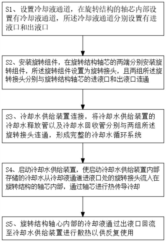
[0026] The present invention provides such Figure 1-3 A shaft core internal cooling method for a rotating structure, comprising the steps of:

[0027] S1. A cooling liquid channel is provided. A cooling liquid channel is provided inside the shaft core of the rotating structure, and the cooling liquid channel is respectively provided with a liquid inlet and a liquid outlet;

[0028] The setting of the coolant ...


PUM


Abstract

The invention discloses an internal cooling method for a shaft core of a rotating structure. The internal cooling method comprises the following steps of S1, arranging a cooling liquid channel, namely arranging the cooling liquid channel inside the shaft core of the rotating structure, and correspondingly forming a liquid inlet and a liquid outlet in the cooling liquid channel; S2, installing a rotating assembly; S3, connecting a cooling water supply device; S4, starting the cooling water supply device; and S5, enabling the cooling liquid in the shaft core of the rotating structure to flow back to the cooling water supply device through the liquid outlet for heat dissipation for repeated use. According to the internal cooling method, the shaft core is used for cooling, the face generating heat can be directly used for conducting heat to the cooling liquid to the maximum extent, the heat is conducted to the cooling liquid along the metal material, and the cooling liquid directly flows back to a radiator through the shaft core for heat dissipation so as to be repeatedly used, the nternal cooling method is particularly suitable for a structure with the internal heat canno be dissipated or difficult to dissipate, and the heat conductivity of the metal material is high, so that the heat dissipation is more facilitated.

Description

technical field [0001] The invention belongs to the field of internal cooling of the shaft core, and more specifically relates to an internal cooling method of the shaft core for a rotating structure. Background technique [0002] At present, common rotating structures include mechanical equipment such as machine tool shafts and augers. For machine tool shafts, the existing machining cooling methods mainly use coolant spray cooling, which can only cool the machined parts and cannot cool the shaft parts. For the auger, most of them are external cooling, the cooling efficiency is low and the time delay is high. Therefore, we propose an internal cooling method for the shaft core for the rotating structure Contents of the invention [0003] The purpose of the present invention is to solve the shortcomings in the prior art, and propose a method for internal cooling of the shaft core used in the rotating structure. This method has high direct cooling efficiency and can ensure th...

Claims


Application Information

Patent Timeline
IPC IPC(8): F25D1/02F25D17/02F25D23/00
CPCF25D1/02F25D17/02F25D23/006
Inventor 韩玉彬成志强李毅松王仕永
Owner 仁新设备制造(四川)有限公司
Learn More