
BAR strip test carrier

A carrier and fixed block technology, which is applied in the field of optical communication, can solve the problems of inaccurate positioning and difficulty in placing it in an accurate position, and achieve the effect of avoiding transshipment loss

Inactive Publication Date: 2021-12-21
QXP TECH INC
View PDF20 Cites 0 Cited by
  • Summary
  • Abstract
  • Description
  • Claims
  • Application Information

AI Technical Summary

Problems solved by technology

However, there is also the problem of inaccurate positioning when loading materials, and there is a disadvantage that it is difficult to place them in an accurate position.

Method used


Image

  • BAR strip test carrier
  • BAR strip test carrier

Examples


Embodiment Construction

[0026] A specific embodiment of the present invention will be described in detail below in conjunction with the accompanying drawings, but it should be understood that the protection scope of the present invention is not limited by the specific embodiment.

[0027] In describing the present invention, it should be understood that the terms "center", "longitudinal", "transverse", "length", "width", "thickness", "upper", "lower", "front", " Rear", "Left", "Right", "Vertical", "Horizontal", "Top", "Bottom", "Inner", "Outer", "Axial", "Radial", "Circumferential" The orientation or positional relationship indicated by etc. is based on the orientation or positional relationship shown in the drawings, and is only for the convenience of describing the technical solution of the present invention and simplifying the description, rather than indicating or implying that the referred device or element must have a specific orientation, Constructed and operative in a particular orientation a...


PUM


Abstract

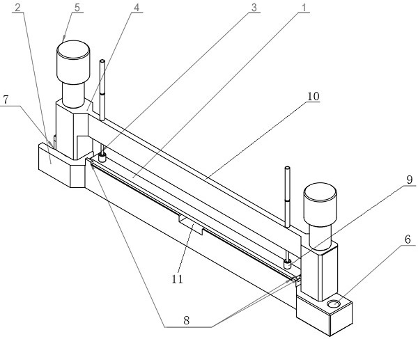
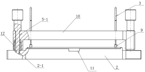
The invention provides a BAR strip test carrier which comprises a BAR strip carrier base, BAR strip pressing block fixing blocks and BAR strip locking pieces, and a groove is formed in the middle of the BAR strip carrier base; the number of the BAR strip pressing block fixing blocks is two, and a cross beam is fixedly connected between the two BAR strip pressing block fixing blocks; a probe with an elastically telescopic lower end is fixed on the cross beam, and an engineering plastic pressing block is fixed at the lower end of the probe; the number of the BAR strip locking pieces is two, and one BAR strip locking piece is arranged between each BAR strip pressing block fixing block and the BAR strip carrier base and used for enabling the BAR strip pressing block fixing blocks to be pressed downwards, so that the BAR strips are pressed on the BAR strip carrier base through the engineering plastic pressing blocks. Accurate positioning and stable clamping of the BAR strips can be achieved, the BAR strips cannot slide and collide in the transferring process, the clamping force can be controlled, and feeding and discharging are facilitated.

Description

technical field [0001] The invention relates to the technical field of optical communication, in particular to a BAR test carrier. Background technique [0002] In the chip production of optical communication, the wafer will not be directly cut into individual chips, but will be cut into strips with a number of N (N≥2), which we call BAR (multiple laser generator combination). And this BAR needs to test the parameters of the chip in it. This test process needs to be carried out on the test equipment after positioning the BAR. [0003] The current conventional BAR positioning method is to place the BAR on the tray through a carrier or a fixture, then place the BAR on a platform with vacuum suction through tweezers or a vacuum pen, and then manually move the BAR to the reference position through tweezers, etc. (Ensure that the light emitting direction is vertical to the detection device) [0004] Conventional carriers are horizontal pallets or pallets with limit slots: [0...

Claims


Application Information

Patent Timeline
Patent Type & Authority Applications(China)
IPC IPC(8): G01R31/28
CPCG01R31/2893G01R31/2886
Inventor 谢小飞范修宏徐之光姚宏鹏程东
Owner QXP TECH INC
Learn More