Industrial waste gas treatment system

A technology of industrial waste gas and treatment system, which is applied in the direction of separation method, use of liquid separation agent, separation of dispersed particles, etc., can solve the problems of endangering human health, harmful effects on the environment and human health, incomplete waste gas treatment, etc., and achieve dust separation efficiency High, complete dust separation, exhaust gas treatment effect

Inactive Publication Date: 2021-12-24
谭金梅
View PDF3 Cites 2 Cited by
  • Summary
  • Abstract
  • Description
  • Claims
  • Application Information

AI Technical Summary

Problems solved by technology

[0002] As we all know, air pollution refers to the discharge of various pollutants into the atmosphere by human production, living activities or nature, and its content exceeds the carrying capacity of the environment, deteriorating the air quality. For health and other issues, my country has a high degree of industrialization, and the treatment of industrial waste gas is of great significance to the governance of the environment. Waste gas purification mainly refers to industrial waste gas such as dust particles, flue gas smoke, odorous gas, and toxic and harmful gases generated in industrial places. The work of treatment, the waste gas emitted by industrial production, often has harmful effects on the environment and human health. Before it is discharged into the atmosphere, purification measures should be taken to make it meet the requirements of the waste gas emission standard. The existing methods for treating dust in industrial waste gas are usually The spraying method is used to deposit dust with water, but the waste gas is too much and the speed is fast, and the waste gas cannot be fully contacted with water, which leads to the problem of incomplete waste gas treatment.

Method used


Image

  • Industrial waste gas treatment system
  • Industrial waste gas treatment system
  • Industrial waste gas treatment system

Examples


Embodiment Construction

[0023] The following are specific embodiments of the present invention and in conjunction with the accompanying drawings, the technical solutions of the present invention are further described, but the present invention is not limited to these embodiments.

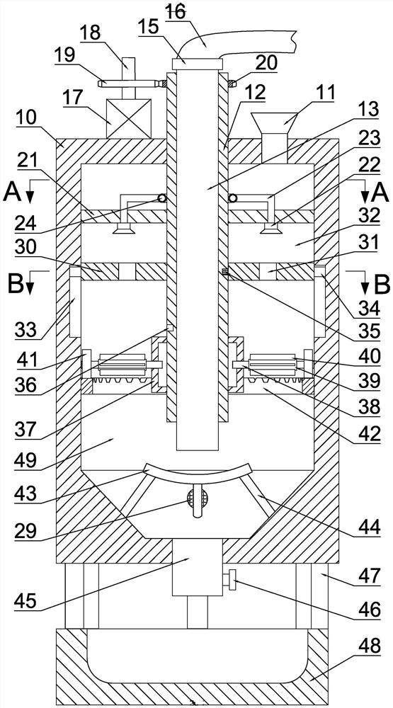
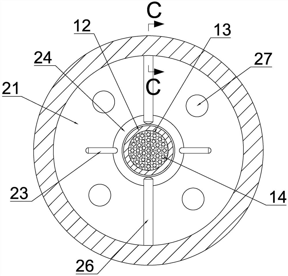
[0024] like figure 1 , figure 2 , Figure 5 As shown, an industrial waste gas treatment system includes a housing 10, an upper opening 11 is provided on the right side of the upper side wall of the housing 10, a motor 17 is fixed on the left side of the upper side wall of the housing 10, and the output end of the motor 17 is provided with an output Shaft 18, the outer side of the output shaft 18 is fixed with a driving gear 19, and the middle part of the upper side wall of the housing 10 is rotated with a crushing cylinder 12, and the upper end of the crushing cylinder 12 is fixed with a driven gear 20, and the driven gear 20 is meshed with the driving gear 19 The inside of the pulverizing cylinder 12 is provided with a...


PUM


Abstract

The invention belongs to the field of air purification treatment equipment, and relates to an industrial waste gas treatment system, which comprises a shell, wherein an opening is formed in the right side of the upper side wall of the shell, a motor is fixedly arranged on the left side of the upper side wall of the shell, an output shaft is arranged at the output end of the motor, a driving gear is fixedly arranged on the outer side of the output shaft, a crushing cylinder is rotationally arranged in the middle of the upper side wall of the shell, a driven gear is fixedly arranged at the upper end of the crushing cylinder, the driven gear is connected with the driving gear in a meshed mode, and a bubble making device is arranged in the crushing cylinder. According to the invention, industrial waste gas is injected into a water body through a gas channel in a gas guide cylinder, bubbles are generated, the water body generates a vortex phenomenon under the action of a smashing device to smash the bubbles so as to completely mix dust in the bubbles with the water body, water flow is discharged into a spraying head through a water discharging device, and secondary separation is conducted on the waste gas discharged into a jet flow cavity, so that a better separation effect is achieved.

Description

technical field [0001] The invention belongs to the field of air purification treatment equipment, in particular to an industrial waste gas treatment system. Background technique [0002] As we all know, air pollution refers to the discharge of various pollutants into the atmosphere by human production, living activities or nature, and its content exceeds the carrying capacity of the environment, deteriorating the air quality. For health and other issues, my country has a high degree of industrialization, and the treatment of industrial waste gas is of great significance to the governance of the environment. Waste gas purification mainly refers to industrial waste gas such as dust particles, flue gas smoke, odorous gas, and toxic and harmful gases generated in industrial places. The work of treatment, the waste gas emitted by industrial production, often has harmful effects on the environment and human health. Before it is discharged into the atmosphere, purification measures ...

Claims


Application Information

Patent Timeline
Patent Type & Authority Applications(China)
IPC IPC(8): B01D47/02B01D47/06
CPCB01D47/021B01D47/06
Inventor 谭金梅
Owner 谭金梅
Why Eureka
Try Eureka