
Movement shifting claw positioning tool

A technology for positioning tooling and movement, applied to positioning devices, manufacturing tools, metal processing equipment, etc., can solve the problems of small size, time-consuming, and deformation of the toggle claws, and reduce the difficulty of loading and unloading, Improve processing efficiency and avoid deformation

Active Publication Date: 2021-12-24
TIANJIN SEAGULL WATCH CO LTD
View PDF5 Cites 0 Cited by
  • Summary
  • Abstract
  • Description
  • Claims
  • Application Information

AI Technical Summary

Problems solved by technology

Limited by the internal space of the movement, the size of the existing toggle claw is relatively small, its length and width are usually only a few millimeters, and its thickness is usually only a few hundred microns or even tens of microns, so the shaft hole will be greatly increased Difficulty in fixing the limit during processing
When using traditional positioning tooling to limit the position, in order to avoid the bending of the toggle claw, the staff need to spend a lot of time to complete the loading and unloading work
In addition, the staff also need to consider the relationship between the clamping force of the tooling and the yield strength of the toggle claw during the loading process, so as to avoid deformation of the toggle claw due to excessive clamping force, which will seriously affect the quality of the toggle claw. Processing efficiency

Method used


Image

  • Movement shifting claw positioning tool
  • Movement shifting claw positioning tool
  • Movement shifting claw positioning tool

Examples


Embodiment Construction

[0040] It should be noted that, in the case of no conflict, the embodiments of the present invention and the features in the embodiments can be combined with each other.

[0041] In describing the present invention, it should be understood that the terms "center", "longitudinal", "transverse", "upper", "lower", "front", "rear", "left", "right", The orientations or positional relationships indicated by "vertical", "horizontal", "top", "bottom", "inner", "outer", etc. are based on the orientation or positional relationships shown in the drawings, and are only for the convenience of describing the present invention Creation and simplification of description, rather than indicating or implying that the device or element referred to must have a specific orientation, be constructed and operate in a specific orientation, and therefore should not be construed as limiting the invention. In addition, the terms "first", "second", etc. are used for descriptive purposes only, and should no...


PUM


Abstract

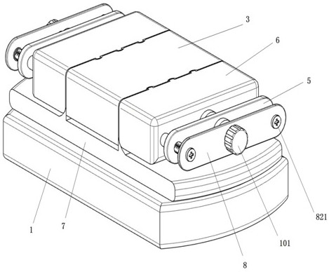
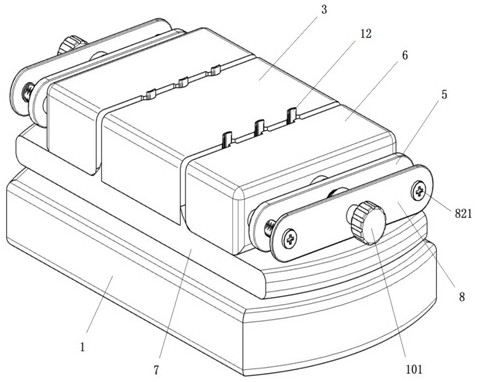
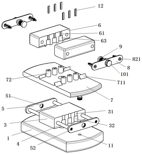
The invention provides a movement shifting claw positioning tool. The movement shifting claw positioning tool comprises a base, a clamping assembly, a jacking plate and an extrusion assembly. The base comprises a bearing seat, a connecting shaft and a center block, and the bottom face of the center block is connected with the top face of the bearing seat through the connecting shaft. The clamping assembly comprises a guide rod, a limiting plate and a clamping block, one end of the guide rod is connected with the side wall of the center block, the other end of the guide rod is connected with the limiting plate, and the clamping block is arranged on the guide rod in a sliding manner. The jacking plate is arranged on the connecting shaft in a liftable manner, and a separation block is arranged on the top face of the jacking plate. The extrusion assembly comprises an adjusting plate, an extrusion sleeve and an operation rod, the adjusting plate is arranged at one side of the limiting plate, one end of the operation rod is inserted into the extrusion sleeve, an operation block is arranged on the operation rod, and a driving groove and an annular cutting groove used for containing the operation block are formed in the extrusion sleeve. According to the movement shifting claw positioning tool, the loading and unloading difficulty of a shifting claw can be reduced, and the shifting claw is prevented from being damaged.

Description

technical field [0001] The invention belongs to the field of watch parts processing equipment, and in particular relates to a movement claw positioning tool. Background technique [0002] The movement is the core component inside the watch. There are multiple components such as the driving system, the transmission wheel system, and the display system inside the movement. When working, the mainspring inside the drive system converts the elastic potential energy into mechanical energy and releases it, then transmits the energy to the inside of the display system through the drive train, and finally drives the hour, minute and second hands inside the display system to move. [0003] In order to enrich the functions of the watch, additional mechanisms such as a calendar will be provided inside the existing movement, and a toggle claw will also be added on the wheel shaft of the relevant transmission wheel train. After the transmission wheel train rotates for a certain period, t...

Claims


Application Information

Patent Timeline
IPC IPC(8): B23Q3/00
CPCB23Q3/00
Inventor 秦卫东宋鸿文朱春彪刘金鹏庞磊
Owner TIANJIN SEAGULL WATCH CO LTD
Learn More