

Preparation method of emulsion explosive containing calcium salt and preparation device thereof
A technology for emulsified explosives and preparation equipment, which is applied in the direction of explosives processing equipment, explosives, explosive composite components, etc., to achieve the effects of increasing emulsification speed, reducing manufacturing costs, and saving time and cost
- Summary
- Abstract
- Description
- Claims
- Application Information
AI Technical Summary
Problems solved by technology
Method used
Image

Examples
specific Embodiment approach 1
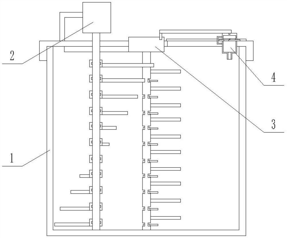
[0021] Specific implementation mode one: as Figure 1-7 As shown, this embodiment describes a preparation device for emulsion explosives containing calcium salts, including a storage tank 1, a stirring device I2, a stirring device II3 and an intermittent feeding device 4; the center of the storage tank 1 is provided with a stirring device II3 , the eccentric position of the storage tank 1 is provided with a stirring device I2, and the stirring device I2 and the stirring device II3 cooperate with each other; the intermittent feeding device 4 is arranged on the upper end of the storage tank 1, and the intermittent feeding device 4 and the stirring device Ⅱ3 connection.
specific Embodiment approach 2
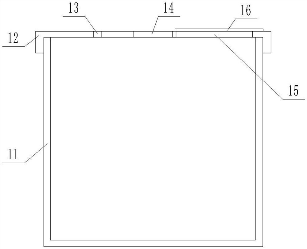
[0022] Specific implementation mode two: as Figure 1-7 As shown, this embodiment is a further description of specific embodiment one. The storage tank 1 includes a tank body 11, a cover 12 and a rack 16; the cover 12 is screwed to the upper end of the tank body 11, and the cover 12 A round hole I14 is provided at the center of the top of the top, and round holes II13 and chute 15 are respectively provided on both sides of the round hole I14;
specific Embodiment approach 3
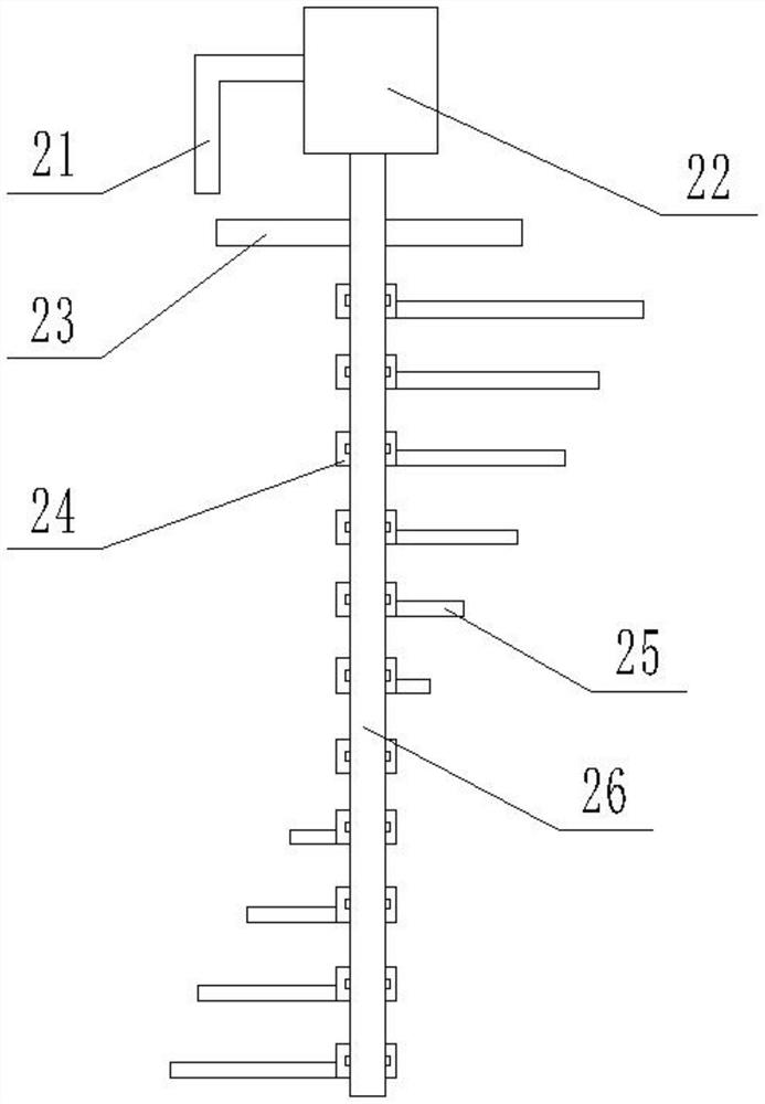
[0023] Specific implementation mode three: as Figure 1-7 As shown, this embodiment is a further description of specific embodiment one. The stirring device I2 includes a motor bracket 21, a motor 22, a gear I23, a connecting ring 24, a plurality of stirring rods I25 and a fixed rod 26; the motor 22 is fixedly connected to the cover 12 through the motor bracket 21, the output shaft of the motor 22 passes through the round hole II13 and is fixedly connected with a fixed rod 26; the fixed rod 26 is fixedly connected with a gear I23 and the fixed rod 26 is uniform from top to bottom A plurality of connecting rings 24 are arranged; each connecting ring 24 is fixedly connected with a corresponding stirring rod I25; the side of each stirring rod I25 is provided with a slot.
[0024] Specific implementation mode four: as Figure 1-7 As shown, this embodiment is a further description of Embodiment 1. Each connecting ring 24 includes a ring 241, a stopper I 243 and a spring 244; the f...
PUM
 Abstract
Description
Claims
Application Information