Main beam applied to wind power blade, wind power blade and forming method thereof

A technology for wind power blades and forming methods, which is applied in wind power generation, wind power engines, machines/engines, etc., and can solve problems affecting the quality of wind power blade forming

Pending Publication Date: 2021-12-28
SHANGHAI ELECTRIC WIND POWER GRP CO LTD
View PDF4 Cites 0 Cited by
  • Summary
  • Abstract
  • Description
  • Claims
  • Application Information

AI Technical Summary

Problems solved by technology

[0006] The technical problem to be solved by the present invention is to overcome the defect that the forming quality of wind power blades is affected by laying continuous felt under the main girder to dr

Method used


Image

  • Main beam applied to wind power blade, wind power blade and forming method thereof
  • Main beam applied to wind power blade, wind power blade and forming method thereof
  • Main beam applied to wind power blade, wind power blade and forming method thereof

Examples


Embodiment Construction

[0063] The present invention will be further described below through specific embodiments combined with the accompanying drawings, but the present invention is not limited to the scope of the following embodiments.

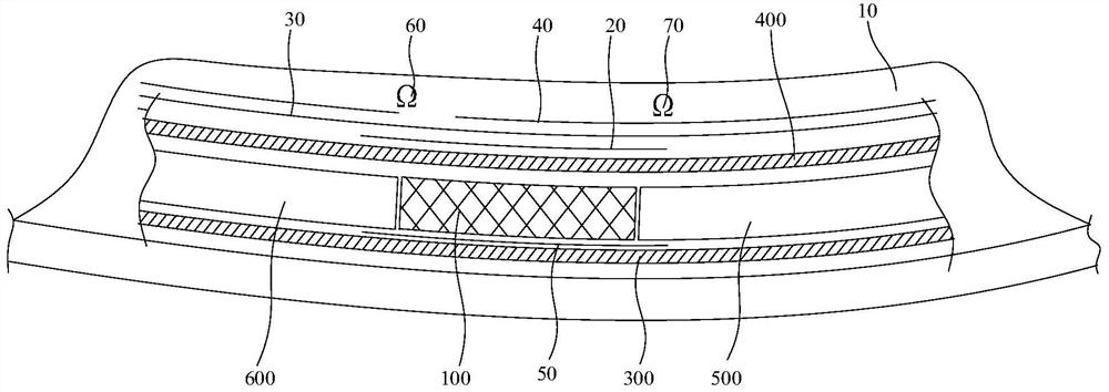
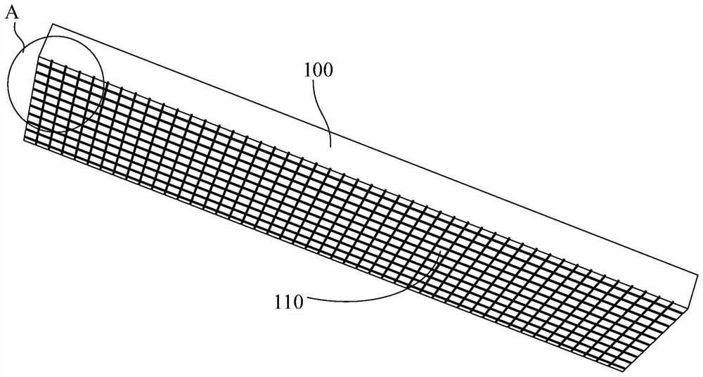
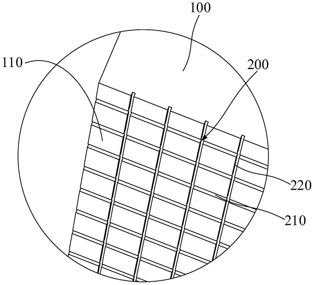
[0064] Such as Figure 2-3 Shown is a main girder 100 disclosed in the embodiment of the present invention, and the main girder 100 is used for wind power blades. The main girder 100 has a lower surface 110 placed downward when the wind turbine blade is formed, the lower surface 110 of the main girder 100 is provided with a plurality of first grooves 200 extending from one end of the main girder 100 to the other end.

[0065] The main beam 100 of the wind power blade adopts the above structure to have the following advantages: First, grooves are provided on the lower surface 110 of the main beam 100, and by controlling the structure and size of the groove, the main beam 100 is lowered during the forming process of the wind power blade. The resin flow velocity on...


PUM

PropertyMeasurementUnit
Spacingaaaaaaaaaa
Depthaaaaaaaaaa
Widthaaaaaaaaaa

Abstract

The invention discloses a main beam applied to a wind power blade, the wind power blade and a forming method thereof. The main beam is provided with a lower surface which is placed downwards when the wind power blade is formed; a plurality of first grooves are formed in the lower surface of the main beam; the first grooves extend from the end portion of one end of the main beam to the end portion of the other end of the main beam. According to the main beam of the wind power blade, the structure is adopted; the structural defects such as the dry yarn defect caused by resin wrapping of the wind power blade can be avoided; and compared with forming of the traditional main beam, the forming period of the wind power blade can be shortened; and the structural performance can be enhanced.

Description

technical field [0001] The invention relates to the field of wind power generation equipment, in particular to a main girder for a wind power blade, a wind power blade and a forming method thereof. Background technique [0002] In wind power blade molding, conventional methods such as figure 1 As shown, the continuous felt is laid on the lower surface of the main beam to drive the resin flow on the lower surface of the main beam. The flow rate of the resin on the lower surface of the main beam is much lower than that on the upper surface, and it is easy to form resin enveloping on the lower surface of the main beam and cause dry yarn defects. A common solution is to disconnect the diversion net on the upper surface of the main beam to slow down the flow of resin on the upper surface of the main beam, but this solution cannot change the flow rate of the resin on the lower surface of the main beam, which will prolong the product infusion time, thereby prolonging the blade mold...

Claims


Application Information

Patent Timeline
IPC IPC(8): B29C70/36B29C70/54B29C37/00F03D80/00
CPCB29C70/36B29C70/54B29C37/0064B29C37/0092F03D80/00Y02E10/72
Inventor 文欢齐志攀王国军白宏伟
Owner SHANGHAI ELECTRIC WIND POWER GRP CO LTD
Why Eureka
Try Eureka