PE film automatic splitting machine

A dividing machine, automatic technology, applied in the direction of cutting and unsealing, packaging, transportation and packaging, can solve the problems of time-consuming, waste of manpower, etc., and achieve the effect of improving production efficiency, reasonable structure and easy realization.

Active Publication Date: 2021-12-28
苏州盈科电子有限公司
View PDF10 Cites 0 Cited by
  • Summary
  • Abstract
  • Description
  • Claims
  • Application Information

AI Technical Summary

Problems solved by technology

However, after the material is transported to the destination, it is still necessary to manually dismantle the film. This action is not only time-consuming, but also wastes manpower. Therefore, in order to reduce the waste of human resources and improve production efficiency, we invented a machine that can automatically disassemble the PE film. mechanism

Method used


Image

  • PE film automatic splitting machine
  • PE film automatic splitting machine
  • PE film automatic splitting machine

Examples


Embodiment 1

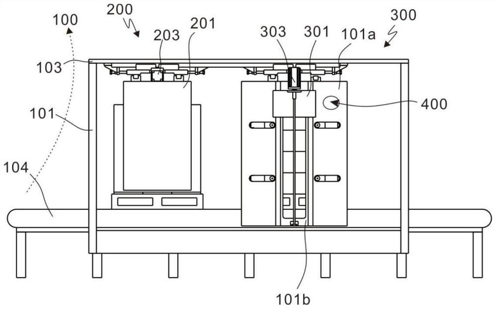
[0030] refer to figure 1 , 2 , is the first embodiment of the present invention, which provides a PE film automatic splitting and dividing machine, including a support module 100 , a sorting module 200 and a cutting module 300 .

[0031] The support module 100 includes a first support frame 101 and a second support frame 102 arranged symmetrically, and a top plate 103 for connecting the first support frame 101 and the second support frame 102, between the first support frame 101 and the second support frame 102 A certain space is formed between the first support frame 101 and the second support frame 102, and a transfer table 104 is arranged between the first support frame 101 and the second support frame 102. The goods are piled on the cargo board and then placed on the transfer table 104. 104, that is, transfer from one end of the support module 100 to the other end of the support module 100.

[0032] When transporting on the conveyor table 104, there are two processes in ...

Embodiment 2

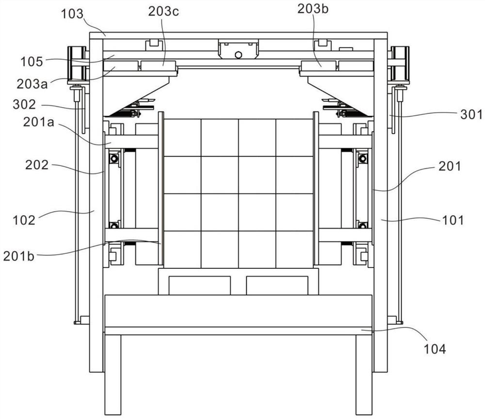
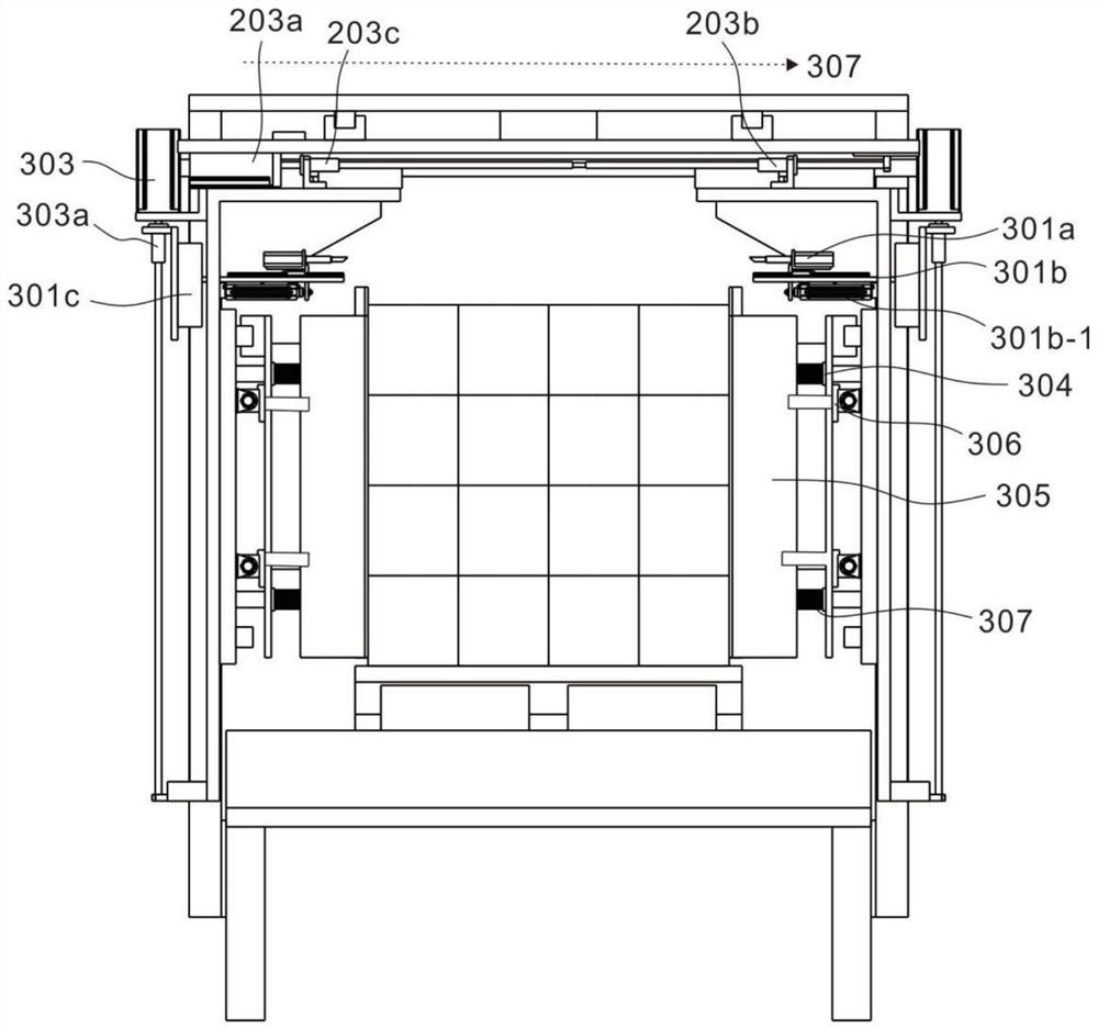
[0039] refer to figure 1 , 3 And 4, is the second embodiment of the present invention, this embodiment is based on the previous embodiment, the first supporting frame 101 and the second supporting frame 102 are all provided with fixed side plate 101a, the first cutting part 301 and the second cutting The member 302 is movably arranged on the fixed side plate 101a.

[0040] The first cutting part 301 and the second cutting part 302 have the same structure, and the first cutting part 301 includes an ultrasonic knife 301a, a bracket 301b and a slider 301c. Specifically, the fixed side plate 101a is provided with a slide rail 101b, the slide block 301c is installed on the slide rail 101b and connected to the bracket 301b, the ultrasonic knife 301a is installed on the bracket 301b, the bottom of the bracket 301b is provided with a first cylinder 301b-1, and the second A cylinder 301b-1 is connected to the ultrasonic scriber 301a. The first cylinder 301b-1 can drive the position o...

Embodiment 3

[0045] refer to Figure 4~7 , is the third embodiment of the present invention, which is based on the previous embodiment, and further includes a locking module 400, the locking module 400 includes two clamping blocks 402 and a manipulation member 403 that are pushed toward a circular plate 401, symmetrically arranged.

[0046] The fixed side plate 101a is provided with vertical slots 101a-2, the number of vertical slots 101a-2 is set to two and the two vertical slots 101a-2 are arranged in the vertical direction, pushed to the circular plate 401 and installed on the fixed side plate 101a to rotate Connection, the center of the push-toward circular plate 401 is connected to the area between the two vertical grooves 101 a - 2 , and the vertical grooves 101 a - 2 are arranged symmetrically with respect to the push-toward circular plate 401 .

[0047] Two straight notches 401a are arranged on the upper circumference of the pushing circular plate 401. The straight notches 401a are...


PUM


Abstract

The invention discloses a PE film automatic splitting machine. The PE film automatic splitting machine comprises a supporting module, an arrangement module and a cutting module; the supporting module comprises a first supporting frame, a second supporting frame and a top plate, the first supporting frame and the second supporting frame are symmetrically arranged, the top plate is used for being connected with the first supporting frame and the second supporting frame, and a conveying table is arranged between the first supporting frame and the second supporting frame; the arrangement module comprises a first supporting plate, a second supporting plate and a first driving part connected with the first supporting plate and the second supporting plate, wherein the first supporting plate and the second supporting plate are the same in structure and are symmetrically arranged; and the cutting module comprises a first cutting piece and a second cutting piece which are the same in structure and are symmetrically arranged, the first cutting piece is fixed to the first supporting frame, and the second cutting piece is fixed to the second supporting frame. An implementation mode that the structure is reasonable, implementation is easy, control is simple and reliable, and cost is low is provided, and automatic cutting operation can be carried out according to material sizes and PE film positions; and the problem of manpower resource waste during manual disassembling of PE wrapping films is solved, and the production efficiency is improved.

Description

technical field [0001] The invention relates to the technical field of industrial automation, in particular to a PE film automatic splitting and dividing machine. Background technique [0002] PE stretch film has good protection performance, good fixity, and can be packed with irregular items. At the same time, it has self-adhesiveness and can pack items tightly; the stretch film packaging is beautiful, which can make hard products stick closely and soft products shrink ; At the same time, it can effectively save packaging costs, reduce labor intensity of workers, and improve packaging efficiency and grades. [0003] Due to the above characteristics of PE stretch film, at present, after the materials on the pallets of logistics warehouses and factories are stacked, PE stretch film is wound manually or automatically by winding machines. However, after the material is transported to the destination, it is still necessary to manually dismantle the film. This action is not only...

Claims


Application Information

Patent Timeline
Patent Type & Authority Applications(China)
IPC IPC(8): B65B69/00
CPCB65B69/0033Y02W30/62
Inventor 钟火炎
Owner 苏州盈科电子有限公司
Why Eureka
Try Eureka