Centrifugal compressor shaft system, centrifugal compressor and air conditioner

A centrifugal compressor and shafting technology, applied in the field of compressors, can solve problems such as the reduction of shafting stability, and achieve the effect of improving stability and reliability

Pending Publication Date: 2021-12-28
GREE ELECTRIC APPLIANCES INC
View PDF0 Cites 2 Cited by
  • Summary
  • Abstract
  • Description
  • Claims
  • Application Information

AI Technical Summary

Problems solved by technology

However, the increase in speed and load will cause the shafting to run closer and closer to the critical speed, which will eventually lead to a decrease in the stability of the shafting

Method used


Image

  • Centrifugal compressor shaft system, centrifugal compressor and air conditioner
  • Centrifugal compressor shaft system, centrifugal compressor and air conditioner
  • Centrifugal compressor shaft system, centrifugal compressor and air conditioner

Examples


Embodiment Construction

[0038] In order to make the above objects, features and advantages of the present invention more comprehensible, specific implementations of the present invention will be described in detail below in conjunction with the accompanying drawings. In the following description, numerous specific details are set forth in order to provide a thorough understanding of the present invention. However, the present invention can be implemented in many other ways different from those described here, and those skilled in the art can make similar improvements without departing from the connotation of the present invention, so the present invention is not limited by the specific embodiments disclosed below.

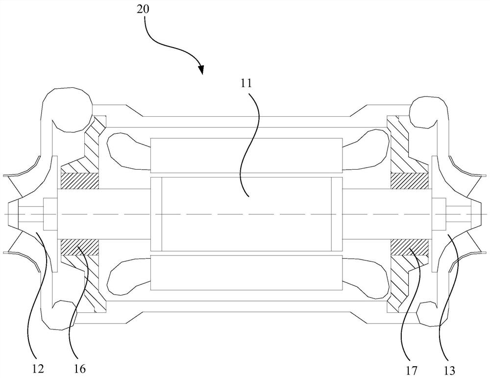
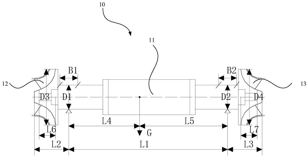
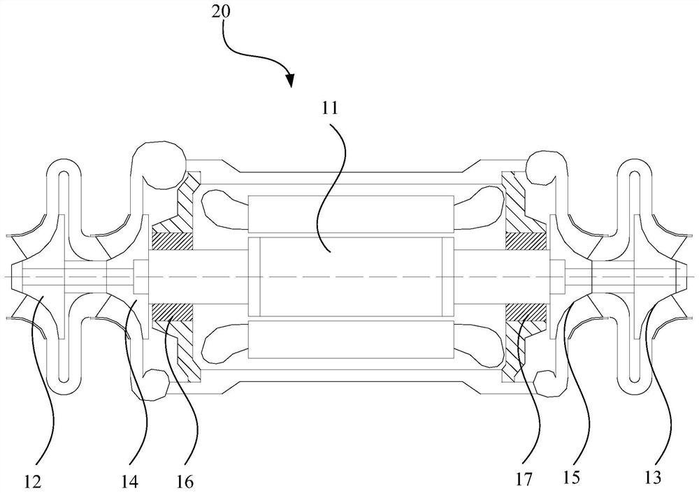
[0039] Such as figure 1 and figure 2 As shown, in one embodiment, a shafting 10 of a centrifugal compressor 20 is provided, including:

[0040] The rotating shaft 11 is provided with a first impeller assembly, a first supporting member 16 , a second supporting member 17 and a second im...


PUM


Abstract

The invention relates to a centrifugal compressor shaft system, a centrifugal compressor and an air conditioner. Through matching design of all geometric parameters of the shaft system, the shaft system can stably operate even under the conditions of high rotating speed and high load, and the use stability and reliability are improved. Specifically, the cantilever length ratios L2/L1 and L3/L1 of the shaft system, the installation width ratios B1/L2 and B2/L3 of a supporting piece, the width-diameter ratios B1/D1 and B2/D2 of the supporting piece, the gravity center shift rate abs (L4-L5)/(L1/2) of the shaft system, and the length-diameter ratios L6/D3 and L7/D4 of an impeller are designed.

Description

technical field [0001] The invention relates to the technical field of compressors, in particular to a centrifugal compressor shaft system, a centrifugal compressor and an air conditioner. Background technique [0002] In the centrifugal compressor, the impeller rotates at high speed to do work for the gas, and the gas is thrown out under the action of the centrifugal force, and the thrown gas has a relatively high pressure and speed. The rotation of the impeller is driven by the rotating shaft in the centrifugal compressor. With the development of science and technology, according to the actual needs of consumers, the performance requirements for compressor speed and load are constantly increasing in various use environments. However, the increase of speed and load will cause the shafting to run closer and closer to the critical speed, which will eventually lead to a decrease in the stability of the shafting. Contents of the invention [0003] Aiming at the problem of r...

Claims


Application Information

Patent Timeline
Patent Type & Authority Applications(China)
IPC IPC(8): F04D29/05F04D17/10F25B31/00F24F13/00
CPCF04D29/05F04D17/10F25B31/00F24F13/00
Inventor 钟瑞兴蒋楠刘华张治平
Owner GREE ELECTRIC APPLIANCES INC
Why Eureka
Try Eureka