
Method for detecting charging voltage of battery pack

A charging voltage and detection method technology, applied in the field of electronics, can solve the problems that the battery pack is not full, the user cannot know the current power of the battery pack, and the circuit board lacks the voltage calibration function, etc., and achieves the effect of improving the sampling accuracy.

Pending Publication Date: 2021-12-28
JIANGSU DONGCHENG TOOLS TECH CO LTD
View PDF0 Cites 0 Cited by
  • Summary
  • Abstract
  • Description
  • Claims
  • Application Information

AI Technical Summary

Problems solved by technology

[0002] In daily life, when the battery or battery pack or battery pack we use is exhausted, we need to use a charger to charge it. However, during the charging process of a general charger, there is no display on the charger housing, resulting in The user cannot know the current power of the battery pack; or there is a portable display on the charger shell, but because the circuit board in its own MCU controller lacks the voltage calibration function, the AD module converts the voltage analog value at the output of the voltage sampling circuit into After the digital quantity N1, directly compare it with the digital quantity N2 converted by the AD module when the battery pack is full of voltage to judge whether the battery pack is full. If the value of N1 is less than the value of N2, it means that the battery pack is not full, and the value of N1 is displayed on the display. If N1 is greater than or equal to the value of N2, it means that the battery pack is fully charged, and the N2 value and the word full of power are displayed on the display, but the values ​​​​N1 and N2 cannot intuitively and clearly reflect the real-time charging of the battery pack. The voltage value makes it impossible for the user to judge the power of the current battery pack

Method used


Image

  • Method for detecting charging voltage of battery pack
  • Method for detecting charging voltage of battery pack
  • Method for detecting charging voltage of battery pack

Examples


Embodiment Construction

[0030] The terminology used in the present invention is for the purpose of describing particular embodiments only, and is not intended to limit the present invention. For example, the following "up", "down", "left", "right" and other words indicating orientation or positional relationship are only based on the orientation or positional relationship shown in the accompanying drawings, and are only for the convenience of describing the present invention and simplifying the description. It is not to indicate or imply that the referenced circuit elements must have a particular orientation or be constructed and operate in a particular orientation, and thus should not be construed as limiting the invention.

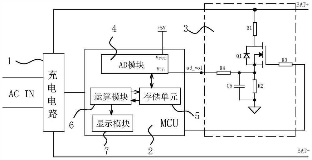
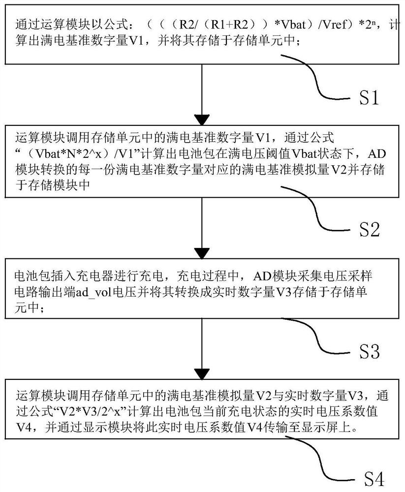
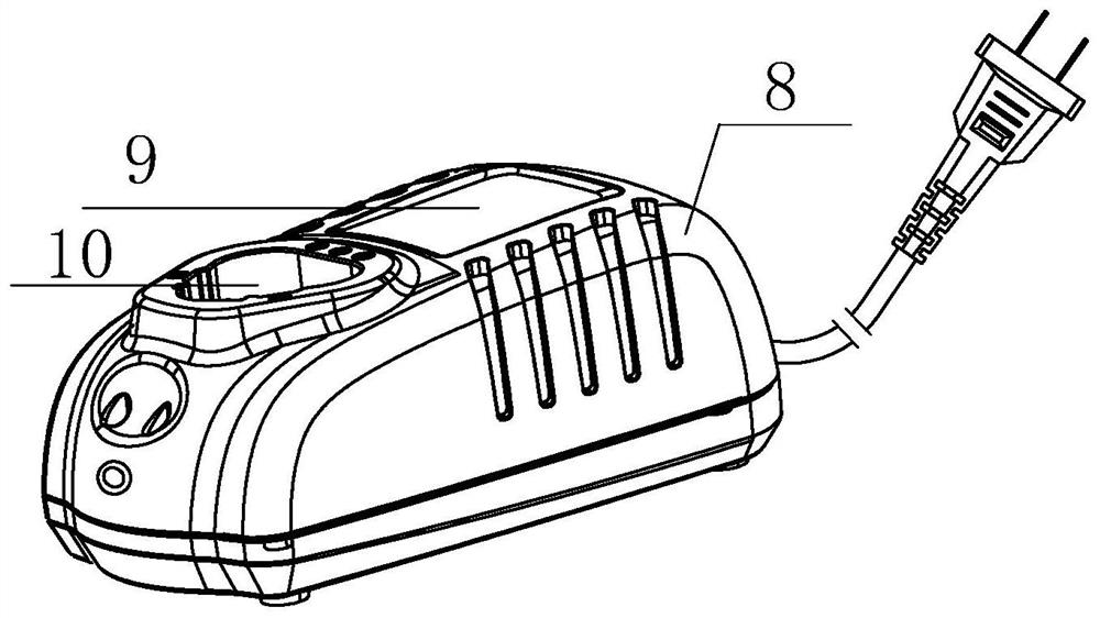
[0031] Such as Figure 1 to Figure 3 A method for detecting the charging voltage of a battery pack is shown, which is used to calibrate the display value of the charger voltage, including the following steps:

[0032] Step 1: The charger is powered on, and the calculation modu...


PUM


Abstract

The invention discloses a method for detecting charging voltage of a battery pack. The method is used for calibrating a voltage display numerical value of a charger, and comprises the following steps: firstly, calculating a full-power reference digital quantity V1 converted by an AD module when the battery pack is in a full-voltage threshold Vbat state by an operation module; secondly, calculating a full-power reference analog quantity V2 corresponding to each full-power reference digital quantity by an operation module; then enabling the AD module to collect a voltage real-time digital quantity V3; and finally, enabling the operation module to calculate a real-time voltage coefficient value V4 of charging of the battery pack, and displaying the real-time voltage coefficient value V4 on the display screen. An existing controller algorithm structure is changed, the real-time digital quantity V3 converted by the AD module is further calibrated through an algorithm formula in the operation module and converted into the real-time voltage coefficient value V4, then the value is displayed on the display screen, the real-time voltage coefficient value V4 can reflect the charging electric quantity of a current battery pack more visually and clearly, the real-time voltage coefficient value V4 can also reflect the charging electric quantity of the current battery pack more visually and clearly, and the voltage value of the battery pack is amplified by 100 times, so that the voltage display precision is further improved.

Description

【Technical field】 [0001] The invention relates to the field of electronics, in particular to a method for detecting the charging voltage of a battery pack. 【Background technique】 [0002] In daily life, when the battery or battery pack or battery pack we use is exhausted, we need to use a charger to charge it. However, during the charging process of a general charger, there is no display on the charger housing, resulting in The user cannot know the current power of the battery pack; or there is a portable display on the charger shell, but because the circuit board in its own MCU controller lacks the voltage calibration function, the AD module converts the voltage analog value at the output of the voltage sampling circuit into After the digital quantity N1, directly compare it with the digital quantity N2 converted by the AD module when the battery pack is full of voltage to judge whether the battery pack is full. If the value of N1 is less than the value of N2, it means that...

Claims


Application Information

Patent Timeline
IPC IPC(8): H02J7/00G01R31/3832G01R19/25
CPCH02J7/0047H02J7/0048G01R31/3832G01R19/2503
Inventor 吴波肖文训
Owner JIANGSU DONGCHENG TOOLS TECH CO LTD
Features
  • Generate Ideas
  • Intellectual Property
  • Life Sciences
  • Materials
  • Tech Scout
  • Unparalleled Data Quality
  • Higher Quality Content
  • 60% Fewer Hallucinations
Learn More