Servo motor driver structure easy to install and installation method thereof
A servo motor and driver technology, applied in the direction of electric components, electrical components, electromechanical devices, etc., can solve the problems of inconvenient installation of the servo motor driver structure, inability to carry out sealing protection, etc., to improve installation convenience, improve installation stability, and improve The effect of seal stability
- Summary
- Abstract
- Description
- Claims
- Application Information
AI Technical Summary
Problems solved by technology
Method used
Image
Examples
Embodiment 1
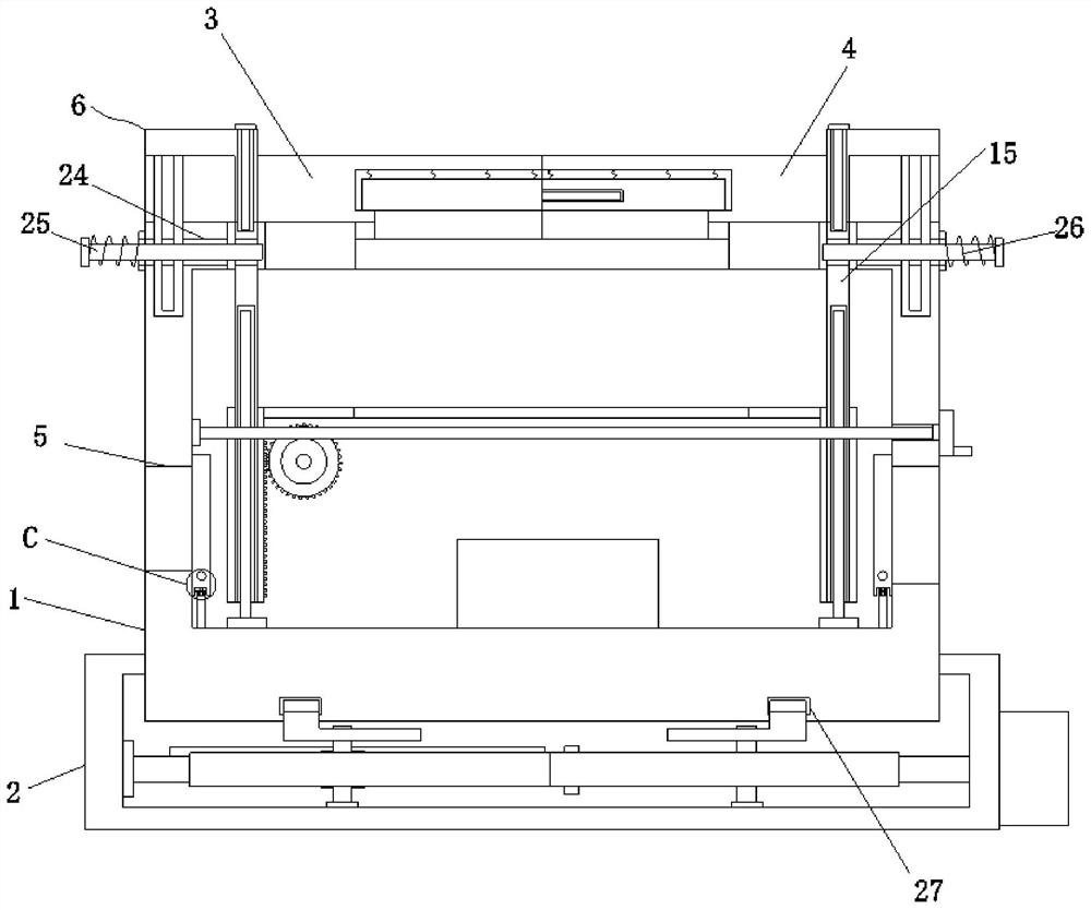
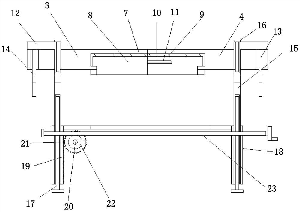
[0050] Embodiment one, by Figure 1 to Figure 10 Given, the present invention includes a driver housing 1, the bottom end of the driver housing 1 is provided with a mounting seat 2, and the top end of the driver housing 1 is provided with a seal, and the driver housing 1 and the mounting seat 2 are connected by a mounting mechanism. Through the design of the installation mechanism, it is convenient to realize the connection between the driver housing 1 and the mounting base 2. The two sides of the bottom end of the driver housing 1 are symmetrically provided with vents 5. Through the design of the vent 5 and the ventilation performance, it is convenient to make the driver case The components inside the body 1 dissipate heat. The inside of the driver housing 1 is provided with a shielding mechanism connected to the vent 5. Through the design of the shielding mechanism, the seal of the vent 5 is realized. The seal includes sealing plate 1 3 and sealing plate 2 4. Slot 7, two fir...
Embodiment 2
[0057] Embodiment two, on the basis of embodiment one, by figure 1 with figure 2 Given, the driver includes a worm wheel 22 and a worm screw 23, the worm wheel 22 is installed on the rotating shaft 20 and is located on one side of the gear one 21, the inside of the driver housing 1 is provided with a worm screw 23 meshed with the worm wheel 22, and one of the first shields One side of the plate 8 is provided with a card slot 10, and the other first shielding plate 8 is provided with a card rod 11 inserted in the card slot 10, the first connecting rod 12 is an L-shaped structure, the insertion rod 13 and the height adjustment Bars 15 are provided with socket slots 14, and the fastening group includes a connection slot 24, a second connecting rod 25 and a spring 26. The top of the driver housing 1 is symmetrically provided with a connection slot 24, and the connection slot 24 is connected to the insertion slot 14. Arranged in parallel, and the inside of the connection groove 2...
Embodiment 3
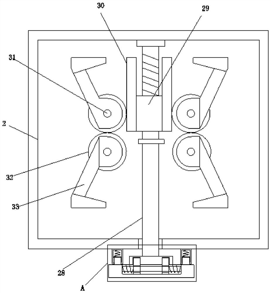
[0060] Embodiment three, on the basis of embodiment one, by figure 1 , image 3 with Figure 4 Given, the installation mechanism includes a fastening groove 27, a screw rod 28, a threaded slide seat 29, a tooth plate 30, a rotating shaft 31, a gear 2 32, a fastening hook 33 and a locking member, and the fastening groove 27 is symmetrically opened in the driver housing 1, the inside of the mounting seat 2 is connected with a screw 28, the threaded slide 29 is threaded on the screw 28, and the two sides of the threaded slide 29 are symmetrically provided with tooth plates 30 that are slidably connected with the mounting base 2 , the inner bottom end of the mounting seat 2 is symmetrically provided with rotating shafts 31 located on both sides of the screw mandrel 28, four rotating shafts 31 are provided with gears 2 32, two adjacent gears 2 32 are engaged and connected, and two of them are gears 2 32 Engaged with the tooth plate 30, the rotating shaft 31 is provided with a fas...
PUM
 Abstract
Description
Claims
Application Information
 - R&D
- Intellectual Property
- Life Sciences
- Materials
- Tech Scout
- Unparalleled Data Quality
- Higher Quality Content
- 60% Fewer Hallucinations
Browse by: Latest US Patents, China's latest patents, Technical Efficacy Thesaurus, Application Domain, Technology Topic, Popular Technical Reports.
© 2025 PatSnap. All rights reserved.Legal|Privacy policy|Modern Slavery Act Transparency Statement|Sitemap|About US| Contact US: help@patsnap.com


