
Ablation device for oncology surgery department

An oncology and surgical technology, applied in the field of surgical ablation devices in oncology, can solve the problem of inability to remove tumors in the digestive tract, and achieve the effect of saving operation time.

Active Publication Date: 2021-12-31
刘贝贝
View PDF6 Cites 0 Cited by
  • Summary
  • Abstract
  • Description
  • Claims
  • Application Information

AI Technical Summary

Problems solved by technology

[0004] The purpose of the present invention is: in order to solve the problem that the traditional ablation device has a simple structure and cannot completely remove the tumor generated in the existing alimentary canal.

Method used


Image

  • Ablation device for oncology surgery department
  • Ablation device for oncology surgery department
  • Ablation device for oncology surgery department

Examples


Embodiment 1

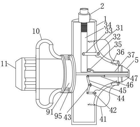
[0030] see Figure 1-7 , an ablation device for surgical oncology, comprising;

[0031] The handheld terminal housing 1 is provided with a threaded seal 5 at the right end of the handheld terminal housing 1. The shape of the handheld terminal housing 1 is T-shaped, and the two vertical corners of the handheld terminal housing 1 are respectively provided with a pressurized liquid valve mechanism 3 and a release valve mechanism. Mechanism 4 ; water injection head 2 , the water injection head 2 is arranged on the top of the hand-held terminal housing 1 and communicates with the pressurized liquid valve mechanism 3 .

[0032] Such as image 3 The shown release mechanism 4 includes a push button 2 41, two press springs 36 for resetting are arranged on the inside of the push button 2 41, and the middle part of the push button 41 is hinged with a first seesaw 43 through a hinge piece 42. One side of the seesaw 43 is fixedly connected with the second seesaw 45, the first seesaw 43 i...

Embodiment 2

[0038] Such as Figure 5 The insertion tube mechanism 6, the left end of the insertion tube mechanism 6 runs through the hand-held end housing 1, the right end of the insertion tube mechanism 6 is provided with an operating end 7, and the operating end 7 includes a reserved end 74 of the ablation head connected to the universal connecting rod 92 , the reserved end 74 of the ablation head is provided with an isolation cover 71, the isolation cover 71 is elastically connected with the reserved end 74 of the ablation head through a pull-back spring 73, an extension end 72 is arranged on the right side of the reserved end 74 of the ablation head, and the operating end The right end of 7 is provided with a peeping operation end 8, and the peeping operation end 8 includes a fisheye end 81, and a retractable storage groove 82 is arranged at the center of the fisheye end 81. The fisheye end 81 also includes a monitoring head 83, and a reserved hole 84 and positioning pin groove 85;

...


PUM


Abstract

The invention discloses an ablation device for the oncology surgery department, and belongs to the technical field of ablation devices for the oncology surgery department. The device comprises a handheld end shell, wherein a threaded sealing piece is arranged at the right end of the handheld end shell, and the handheld end shell is in a T shape. After the device is operated and water is injected into the superficial mucous membrane layer of the esophageal tube wall, a water bag can be bulged on the superficial mucous membrane layer of the esophageal tube wall, so that an operation space is formed by the superficial mucous membrane layer of the esophageal tube wall and a muscle layer, then the superficial mucous membrane layer of the esophageal tube wall is glazed, the tumor on the superficial mucous membrane layer and the muscle layer of the wall surface of the esophagus can be quickly exposed, the problem that the tumor between the superficial mucous membrane layer and the muscle layer of the wall surface of the esophagus cannot be ablated by the existing technical means can be avoided, the tumor is separated from the muscle part, and the ablation is quicker, in addition, the condition that the esophagus is injured due to a direct ablation mode is not needed, and the operation time is saved.

Description

technical field [0001] The invention belongs to the technical field of an ablation device for oncology surgery, in particular to an ablation device for oncology surgery. Background technique [0002] The treatment of tumor ablation is divided into several types, including thermal ablation, cryoablation, and chemical ablation. Thermal ablation includes microwave ablation and radiofrequency ablation, cryoablation is argon-helium knife treatment, and chemical ablation used to be alcohol injection treatment. The main purpose of ablation is to degenerate the local lesions of the tumor. For example, if the tumor is heated to 60°C-80°C or even 100°C with microwave or radio frequency, its tissue will undergo coagulation necrosis to achieve the purpose of locally inactivating the tumor; Cryoablation is the necrosis of tumor tissue through ultra-low temperature; chemical ablation is the necrosis of most or all of the tumor tissue through chemical methods, including drugs. Therefore,...

Claims


Application Information

Patent Timeline
Patent Type & Authority Applications(China)
IPC IPC(8): A61B18/00A61B90/00
CPCA61B18/00A61B90/39A61B2018/00488A61B2018/00577A61B2090/3908A61B2090/3991A61B2090/3983
Inventor 戴晶晶
Owner 刘贝贝
Learn More