Speed difference falling protector provided with reverse locking mechanism and used for high-altitude operation of electric power iron tower
A technology for power towers and high-altitude operations, applied to safety belts, life-saving equipment, etc., can solve the problems of inability to grasp, the fall arrester cannot be lifted, and the safety rope of the fall arrester can be pulled out faster, etc., to save time.
- Summary
- Abstract
- Description
- Claims
- Application Information
AI Technical Summary
Problems solved by technology
Method used
Image
Examples
Embodiment 1
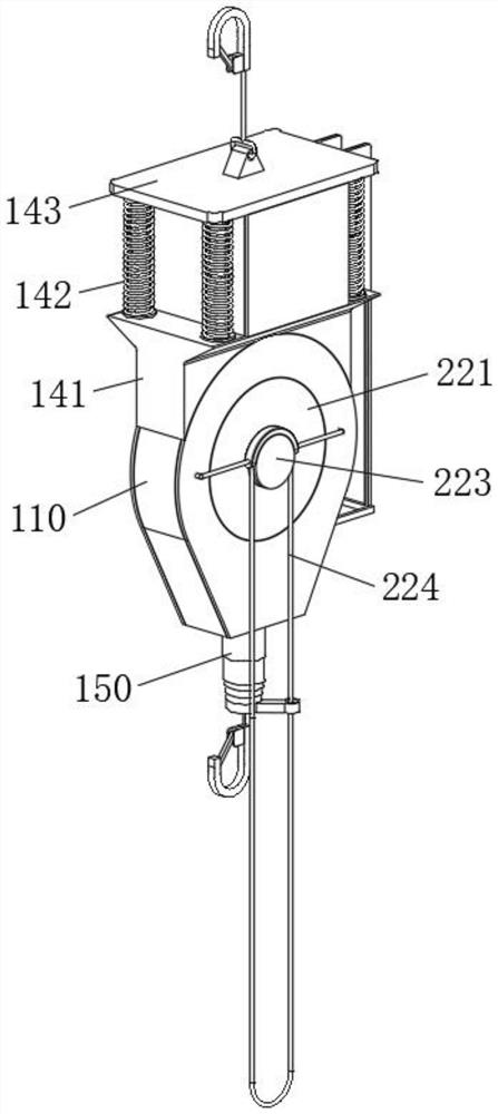
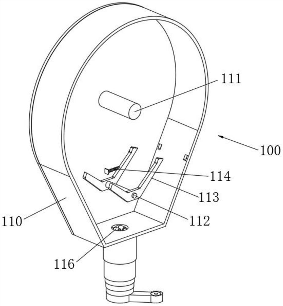
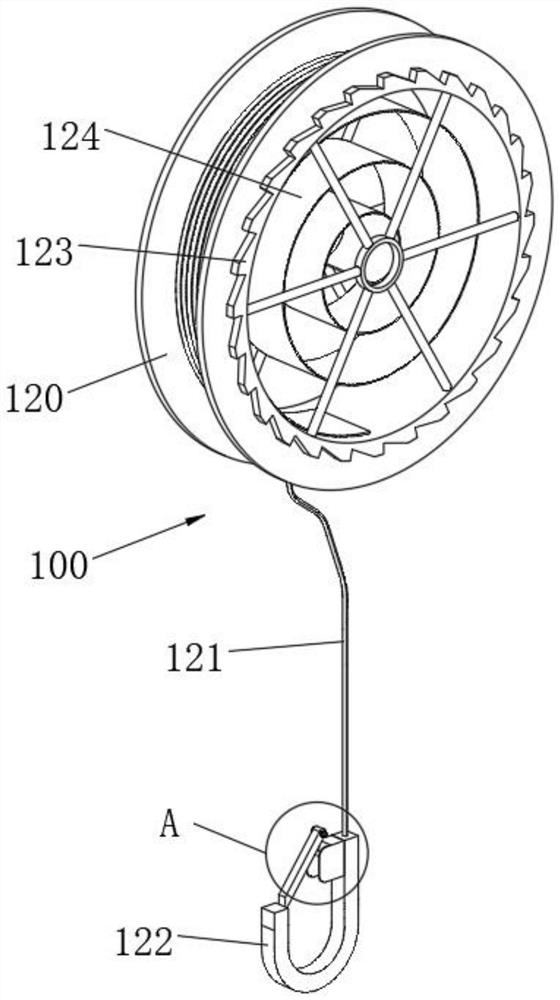
[0050] see Figure 1-Figure 9 As shown, there is provided a speed difference anti-dropping device with a reverse locking mechanism for power tower high-altitude operations, including an anti-dropping device 100 and a lifting device 200 arranged on the side of the anti-dropping device 100, and the anti-dropping device 100 includes a housing 110 and the mounting plate 120, the inner wall of the housing 110 is provided with a mounting shaft 111 and a fixed shaft 112, the outer wall of the fixed shaft 112 is rotatably connected with a pawl 113, the pawl 113 is in a "V" shape structure, and the side wall of the pawl 113 is connected to There is a tension spring 114, one end of the tension spring 114 is connected to the side wall of the housing 110, the top of the housing 110 is connected with a first hook 115, the mounting plate 120 is in a circular structure, and the inner ring of the mounting plate 120 is provided with a The shaft 111 rotates the connected collar, the outer ring ...
Embodiment 2
[0060] In order to improve the stability of the device and prevent the connecting rope 121 from shaking greatly, the following improvements are made on the basis of Embodiment 1:
[0061] see Figure 10 As shown, wherein, the bottom of the housing 110 is located at the outer periphery of the connecting rope 121 and is provided with a telescopic tube 150. The telescopic tube 150 is composed of a plurality of slidingly connected round tubes. The outer wall of one end of the telescopic tube 150 is connected with a transmission rod 151. Sleeved on the outer wall of the driving part 224, the transmission rod 151 is provided with an elastic sleeve 152. The elastic sleeve 152 is preferably made of rubber. A certain friction force is generated between the parts 224, and the elastic sleeve 152 is sleeved on the outer wall of the driving part 224. When the driving part 224 is pulled, the driving part 224 rotates to drive the elastic sleeve 152 to move, and the elastic sleeve 152 drives ...
Embodiment 3
[0063] In order to realize the storage of the driver 224, the following improvements are made on the basis of Embodiment 1:
[0064] see Figure 11 As shown, wherein, the bottom of the top plate 143 is provided with a baffle 160, the top of the fixed block 141 is provided with a slide 161, the surface of the slide 161 is inclined, and the slide 161 is arranged in the baffle 160. When using the device, the driving part 224 is inserted into the surface of the slide plate 161, and then the buffer spring 142 drives the baffle plate 160 through its own elasticity to clamp the driver 224. When the buffer spring 142 deforms, the distance between the baffle plate 160 and the fixed block 141 becomes longer. The driver 224 slides down through the surface of the buffer spring 142 according to its own weight, so that the driver 224 will not affect the operator's construction under normal conditions, and the driver 224 will fall when the operator falls.
PUM
 Abstract
Description
Claims
Application Information
 - R&D
- Intellectual Property
- Life Sciences
- Materials
- Tech Scout
- Unparalleled Data Quality
- Higher Quality Content
- 60% Fewer Hallucinations
Browse by: Latest US Patents, China's latest patents, Technical Efficacy Thesaurus, Application Domain, Technology Topic, Popular Technical Reports.
© 2025 PatSnap. All rights reserved.Legal|Privacy policy|Modern Slavery Act Transparency Statement|Sitemap|About US| Contact US: help@patsnap.com


