
Automobile seat guard plate injection mold

A technology for injection molds and car seats, which is applied to household appliances, other household appliances, household components, etc., can solve the problem that the undercut mechanism cannot realize synchronous demoulding, the tapered hole and the undercut structure cannot be quickly and effectively demoulded, Not applicable etc.

Pending Publication Date: 2021-12-31
NINGBO FANGZHENG TOOL
View PDF5 Cites 6 Cited by
  • Summary
  • Abstract
  • Description
  • Claims
  • Application Information

AI Technical Summary

Problems solved by technology

[0003] At present, in the design of injection molds, products with multi-button and barb structures are often encountered. The usual method is to force release by using inclined tops or swing rods or using the characteristics of materials combined with the product structure to allow a certain elastic deformation space. mold, but these solutions are not suitable for some products. For example, there are tapered holes arranged obliquely in the structure of the car seat panel, and there is also an undercut mechanism in the tapered hole. In this case, simply rely on the inclined top The mechanism can only realize the demoulding of the tapered hole, and the undercut mechanism cannot realize synchronous demoulding, that is, the conventional inclined top mechanism can no longer realize the rapid and effective demoulding of the tapered hole and the undercut structure. It is necessary to develop a new convenient two Mold structure with fast and effective demoulding

Method used


Image

  • Automobile seat guard plate injection mold
  • Automobile seat guard plate injection mold
  • Automobile seat guard plate injection mold

Examples


Embodiment Construction

[0024] In order to make the above objects, features and advantages of the present invention more comprehensible, specific embodiments of the present invention will be described in detail below in conjunction with the accompanying drawings.

[0025] In the description of the present invention, it should be noted that the orientation or positional relationship indicated by the terms "upper end", "lower end", "inner wall" and "outer wall" are based on the orientation or positional relationship shown in the accompanying drawings, and are only In order to facilitate the description of the present invention and simplify the description, it does not indicate or imply that the device or element referred to must have a specific orientation, be constructed and operated in a specific orientation, and thus should not be construed as limiting the present invention. In addition, in the description of the present invention, the terms "first" and "second" are only for convenience of descriptio...


PUM


Abstract

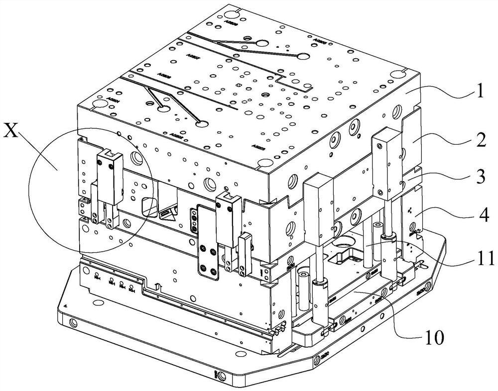
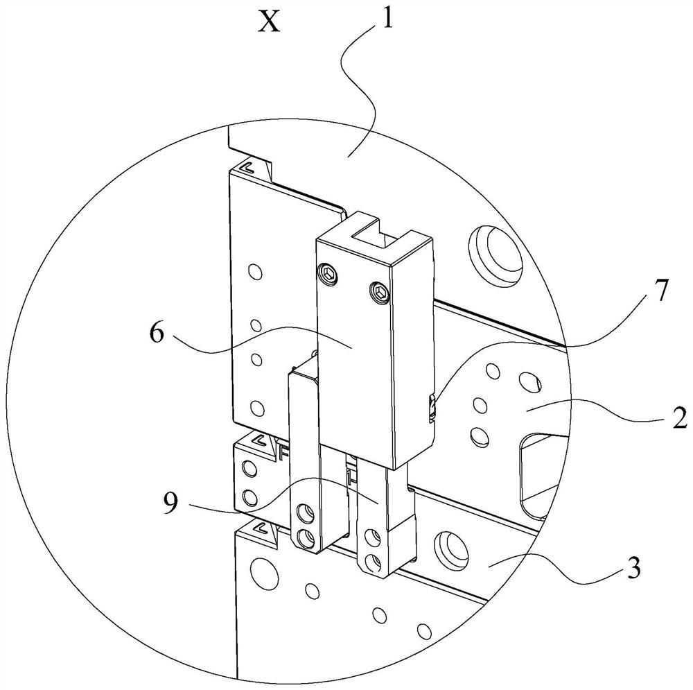
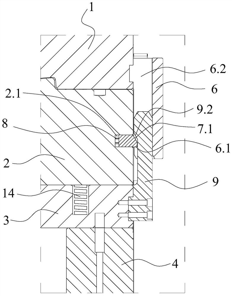
The invention provides an automobile seat guard plate injection mold. The automobile seat guard plate injection mold comprises a movable mold, a fixed mold, a fixed mold base plate and a lower mold base, and an inclined core pulling mechanism is connected to the fixed mold base plate; an ejector plate is arranged on the lower mold base, and an inclined ejector is arranged on the ejector plate; multiple locking blocks are arranged on the outer side wall of the movable mold in the circumferential direction, multiple spring bolts and a first elastic piece are arranged on the fixed mold, and multiple unlocking blocks are arranged on the fixed mold base plate; the unlocking blocks are in sliding fit with the spring bolts in the vertical direction, and when the spring bolts and the unlocking blocks slide to a set distance in the vertical direction, the unlocking blocks are used for driving the spring bolts and the locking blocks to be unlocked; and during mold opening, the movable mold moves upwards, the fixed mold moves upwards at the same time, so that the inclined core pulling mechanism is separated from a product, and when the fixed mold moves upwards to a set distance, the spring bolts and the locking blocks are unlocked. According to the automobile seat guard plate injection mold, rapid, effective and stable demolding of an inclined taper hole in the product and an inverted buckle structure in the taper hole can be achieved at the same time.

Description

technical field [0001] The invention relates to the technical field of injection molds, in particular to an injection mold for an automobile seat guard plate. Background technique [0002] Injection mold is a tool for producing plastic products, and it is also a tool for giving plastic products complete structure and precise dimensions. Injection molding is a processing method used in the mass production of certain complex-shaped parts. Specifically, it refers to injecting heated and melted plastic into a mold cavity under high pressure from an injection molding machine, and after cooling and solidifying, a molded product is obtained. [0003] At present, in the design of injection molds, products with multi-button and barb structures are often encountered. The usual method is to force release by using inclined tops or swing rods or using the characteristics of materials combined with the product structure to allow a certain elastic deformation space. mold, but these soluti...

Claims


Application Information

Patent Timeline
Patent Type & Authority Applications(China)
IPC IPC(8): B29C45/33B29C45/40B29C45/66B29L31/30
CPCB29C45/332B29C45/4005B29C45/66B29C2045/4063B29L2031/3041
Inventor 赖旭龙曾义顺陈聚辉叶宗明王辉黄志高周华民
Owner NINGBO FANGZHENG TOOL
Learn More