
Rib plate unloading type combined steel pile supporting and anchoring structure and application

A technology of ribs and steel piles, applied in sheet pile walls, foundation structure engineering, construction, etc., can solve problems affecting earthwork excavation and basement construction speed, complex structure, long construction period, etc., achieve small deformation, increase resistance Overturning moment, high safety effect

Pending Publication Date: 2021-12-31
HUNAN UNIV OF SCI & ENG
View PDF2 Cites 0 Cited by
  • Summary
  • Abstract
  • Description
  • Claims
  • Application Information

AI Technical Summary

Problems solved by technology

However, the structure of internal support, diagonal support or pull anchor is complicated, and the construction period is long, and the setting of internal support affects the speed of earthwork excavation and basement construction

Method used


Image

  • Rib plate unloading type combined steel pile supporting and anchoring structure and application
  • Rib plate unloading type combined steel pile supporting and anchoring structure and application
  • Rib plate unloading type combined steel pile supporting and anchoring structure and application

Examples


Embodiment 1

[0052] The application of the present invention in deep foundation pit support or cofferdam engineering, its steps are as follows:

[0053] 1) Preparatory work: prefabricated the sub-components of the continuous wall, the parent components and the rib sub-components of the ribs, and the rib parent components, set hydrophobic epoxy on the outer wall of the mortise of the continuous wall sub-components and the inner wall of the female component. Resin coating, transportation of prefabricated parts to the construction site;

[0054] 2) Install the diaphragm wall: Construct the mother component and sub-component in sequence on the side wall of the foundation pit to form a diaphragm wall support structure;

[0055] 3) Install the ribs: Construct the rib sub-components and the rib parent components in sequence on the outside of the continuous wall to the design depth;

[0056] 4) Excavation: Excavate the soil above the ribs and between the ribs until the top surface of the ribs is ...

Embodiment 2

[0065] The application of the present invention in bank revetment slope protection project, its construction steps are as follows:

[0066] a) Preparatory work: prefabricated the sub-components of the diaphragm wall, the mother members and the rib sub-members of the ribs, and the rib mother members. Resin coating, transportation of prefabricated parts to the construction site;

[0067] b) Diaphragm wall installation: Construct mother components and sub-components in sequence at the design position of slope revetment or bank revetment to form a diaphragm wall support structure;

[0068] c) Install the ribs: Construct the rib sub-components and the rib parent components in sequence on the outside of the continuous wall to the design depth;

[0069] d) Excavation: Excavate the soil above the top surface of the ribs and between the ribs until the top surface of the ribs is exposed;

[0070] e) Set the anti-filter layer: set the anti-filter layer or concave-convex drainage board ...


PUM


Abstract

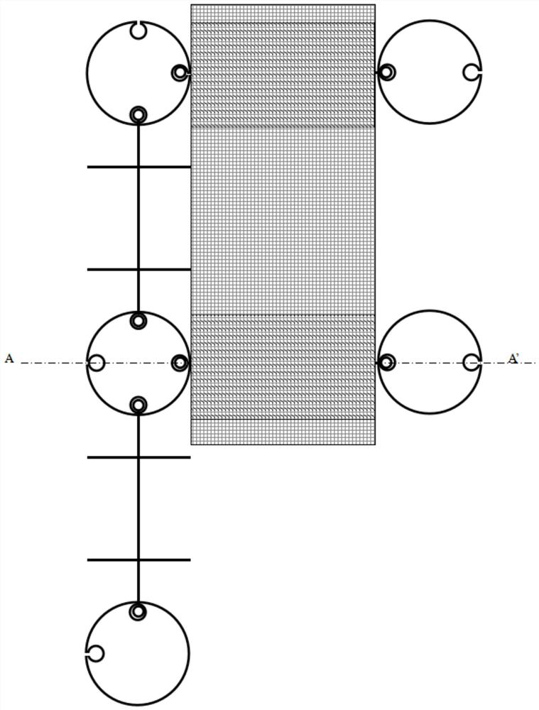
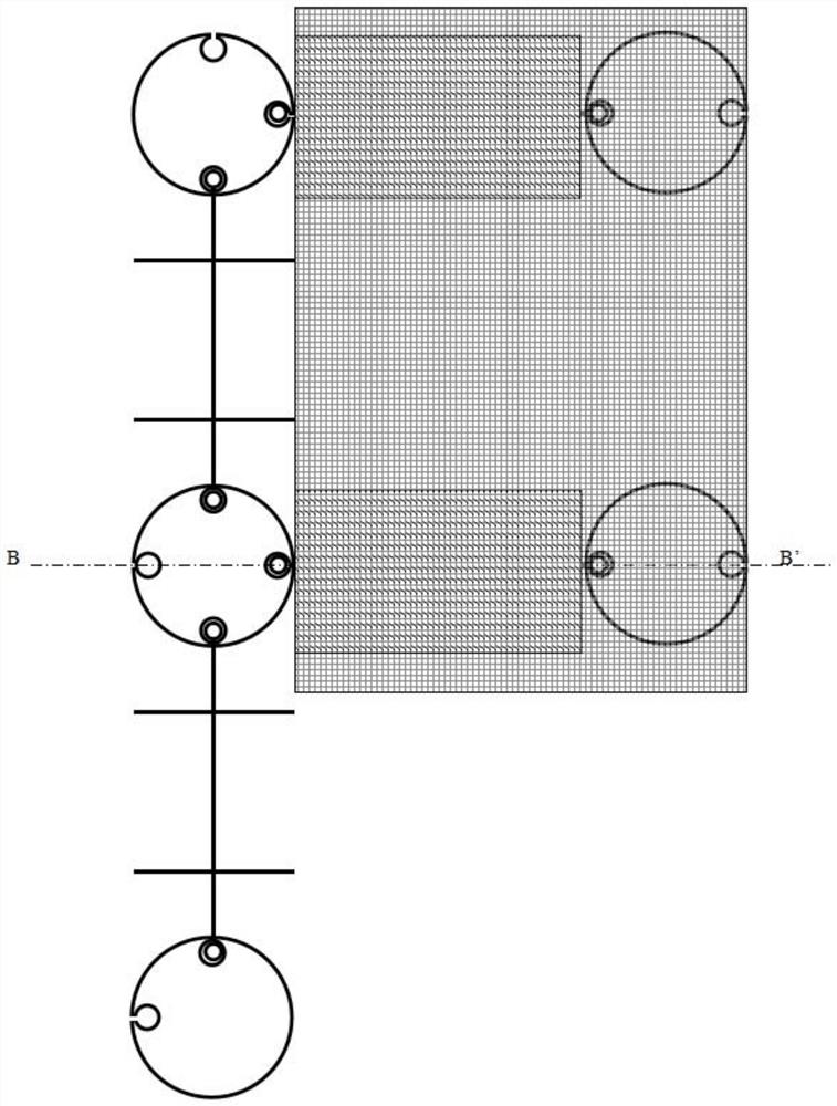
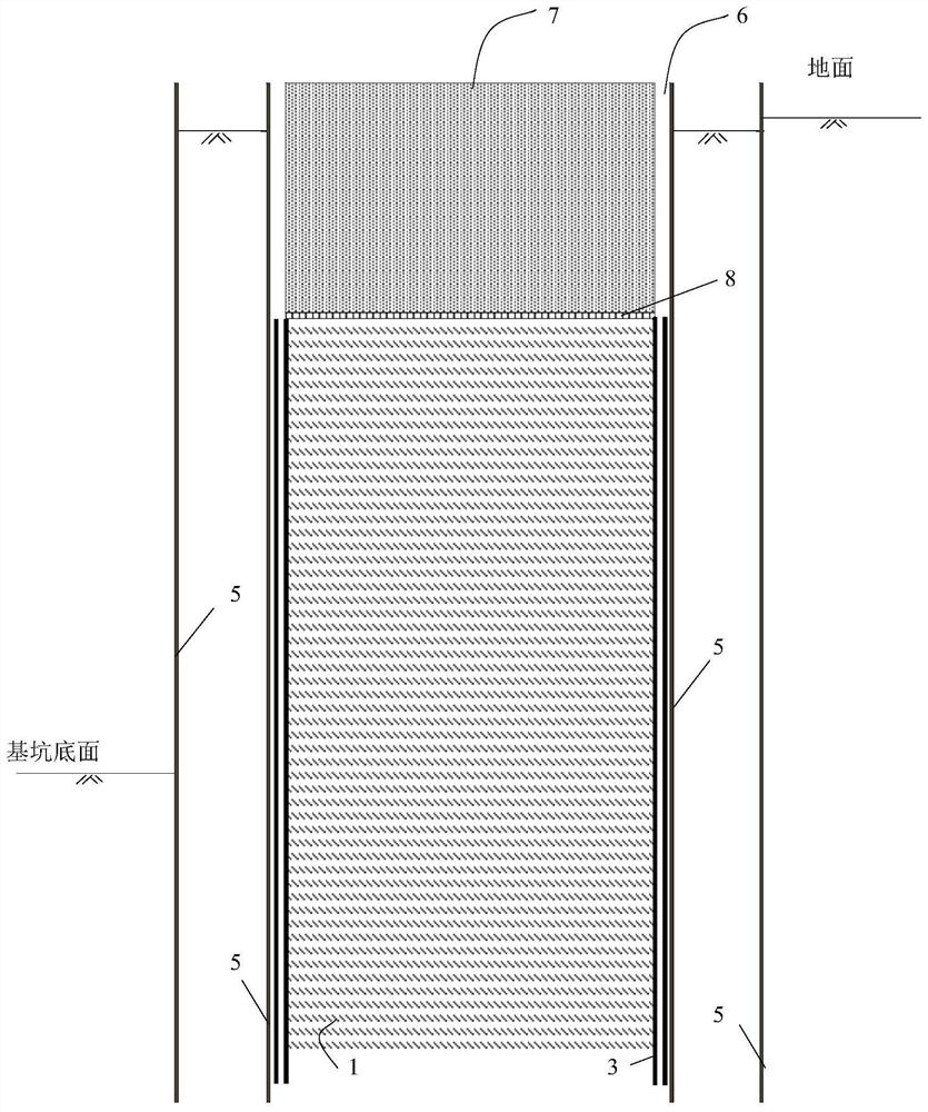
The invention discloses a rib plate unloading type combined steel pile supporting and anchoring structure and application. The rib plate unloading type combined steel pile supporting and anchoring structure comprises a continuous wall, a plurality of rib plates and unloading plates. One ends of the rib plates are connected with the continuous wall, the rib plates are perpendicular to the continuous wall, and the top faces of the rib plates are lower than the top face of the continuous wall; the unloading plates are arranged at the tops of the rib plates and are horizontally arranged; and filling soil is arranged above the unloading plates. The rib plate unloading type combined steel pile supporting and anchoring structure is simple, convenient to construct, low in manufacturing cost and short in construction period, can be used as a recyclable temporary supporting structure to be applied to deep foundation pit supporting or cofferdam engineering, and can further be used as a permanent supporting structure to be applied to bank protection and slope protection engineering.

Description

technical field [0001] The invention relates to the field of foundation pit enclosure protection engineering, cofferdam engineering and bank revetment and slope protection engineering in civil engineering, in particular to a rib plate unloading type composite steel pile anchor structure and its application. Background technique [0002] At present, domestic foundation pit support structures include steel sheet piles, bored pile structures, SMW piles, TRD construction methods, and underground diaphragm walls. The steel sheet pile construction method is widely used in the temporary enclosure of railway bridge piers and foundation pit projects with shallow excavation depth due to its high quality, convenient and fast construction, and reusable characteristics. However, due to the current domestic market [0003] The steel sheet piles are limited by the rigidity of the section and cannot be used in foundation pits with large excavation depths. The most commonly used structures ...

Claims


Application Information

Patent Timeline
IPC IPC(8): E02D17/04E02D19/18E02D19/04E02B3/12E02D5/08E02D5/14
CPCE02D17/04E02D19/18E02D19/04E02B3/12E02D19/185E02D5/08E02D5/14
Inventor 李仁平唐军峰唐雪梅孙明李喆周基
Owner HUNAN UNIV OF SCI & ENG
Learn More