Brightness compensation method, brightness compensation device and brightness compensation system of LED display screen

A technology of LED display and brightness compensation, applied in static indicators, instruments, etc., can solve problems such as affecting the correction effect, and achieve a good correction effect.

Active Publication Date: 2021-12-31
SHENZHEN LIDING PHOTOELECTRIC TECH
View PDF11 Cites 0 Cited by
  • Summary
  • Abstract
  • Description
  • Claims
  • Application Information

AI Technical Summary

Problems solved by technology

[0002] In the existing process of brightness correction for LED display screens, cameras are used to take pictures. The cameras include light filters and photosensitive chips (including but not limited to CMOS and CCD). The relationship between the three can be used for LED display. Screen-filter-photosensitive chip-obtain a target brightness (the brightness value reflected by the light transmittance of the standard curve CIE1931XYZ), but in the actual use process, due to the processing technology of the filter, there will be There is a certain difference between the obtained actual brightness and the required target brightness, and even if there is no problem with the processing technology, when the filter and the photosensitive chip are used in combination, the actual brightness obtained above and the required target will also appear. There is a certain difference in brightness. It can be seen that due to the existence of this problem, for the current LED display calibration, it will directly affect the calibration effect.

Method used


Image

  • Brightness compensation method, brightness compensation device and brightness compensation system of LED display screen
  • Brightness compensation method, brightness compensation device and brightness compensation system of LED display screen
  • Brightness compensation method, brightness compensation device and brightness compensation system of LED display screen

Examples


Embodiment Construction

[0054] The technical solutions in the embodiments of the present invention will be clearly and completely described below in conjunction with the drawings in the present invention. Apparently, the described embodiments are only some of the embodiments of the present invention, not all of them. Based on the embodiments of the present invention, all other embodiments obtained by persons of ordinary skill in the art without making creative efforts belong to the protection scope of the present invention.

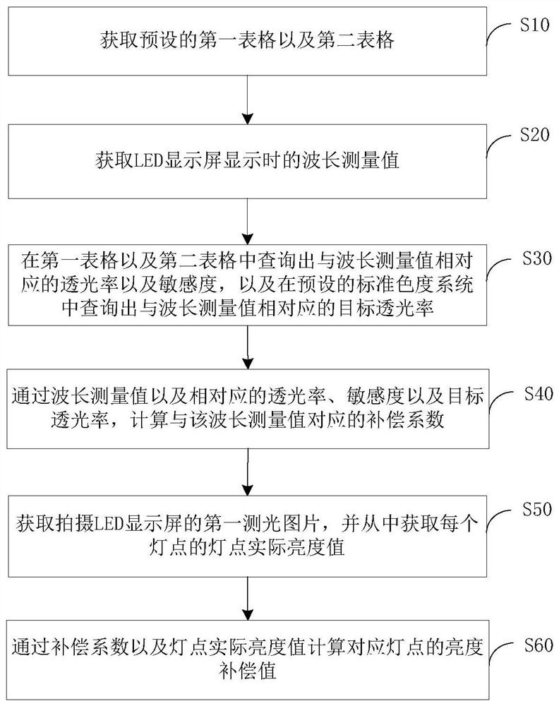
[0055] A brightness compensation method of an LED display screen according to an embodiment of the present invention, such as figure 1 shown, including the following steps:

[0056] Step S10: Obtain the preset first table and second table; the first table is the corresponding relationship between the light transmittance of the filter at different wavelengths and the wavelength value; the second table is the sensitivity of the photosensitive chip at different wavelengths The cor...


PUM


Abstract

The invention relates to the technical field of LED screen correction, and particularly discloses a brightness compensation method, a brightness compensation device and a brightness compensation system for an LED display screen, and the method comprises the steps: obtaining a preset first table and a preset second table; obtaining a wavelength measurement value when the LED display screen displays; querying light transmittance and sensitivity corresponding to the wavelength measurement value in a first table and a second table, and querying target light transmittance corresponding to the wavelength measurement value in a preset standard chromaticity system; calculating a compensation coefficient corresponding to the wavelength measurement value; obtaining a first photometric picture for shooting the LED display screen, and obtaining a lamp point actual brightness value of each lamp point from the first photometric picture; and calculating the brightness compensation value of the corresponding lamp point through the compensation coefficient and the actual brightness value of the lamp point. According to the invention, the problem that the correction effect is influenced due to the brightness difference caused by the optical filter and the photosensitive chip when the LED display screen is corrected is solved, so that the brightness compensation of all lamp points of the LED display screen is realized, and a good correction effect is ensured.

Description

technical field [0001] The invention relates to the technical field of LED screen correction, in particular to a brightness compensation method, a brightness compensation device and a brightness compensation system of an LED display screen. Background technique [0002] In the existing process of brightness correction for LED display screens, cameras are used to take pictures. The cameras include light filters and photosensitive chips (including but not limited to CMOS and CCD). The relationship between the three can be used for LED display. Screen-filter-photosensitive chip-obtain a target brightness (the brightness value reflected by the light transmittance of the standard curve CIE1931XYZ), but in the actual use process, due to the processing technology of the filter, there will be There is a certain difference between the obtained actual brightness and the required target brightness, and even if there is no problem with the processing technology, when the filter and the ...

Claims


Application Information

Patent Timeline
Patent Type & Authority Applications(China)
IPC IPC(8): G09G3/32
CPCG09G3/32G09G2320/0233
Inventor 阮诗安
Owner SHENZHEN LIDING PHOTOELECTRIC TECH
Why Eureka
Try Eureka