Efficient paint dipping device for transformer winding

A transformer winding and varnish dipping technology, which is applied in the field of transformers, can solve the problems of prolonging the varnish dipping process, long soaking time, and lack of drying devices, etc., and achieve the effects of shortening the varnish dipping process, improving automation, and speeding up the process.

Inactive Publication Date: 2021-12-31
江苏士丰电气有限公司
View PDF0 Cites 0 Cited by
  • Summary
  • Abstract
  • Description
  • Claims
  • Application Information

AI Technical Summary

Problems solved by technology

During the manufacturing process of the transformer, its windings need to be dipped in varnish, and all space air gaps are filled with insulating varnish, so that the insulation strength and moisture-proof strength of the windings can be improved, and the heat resistance and heat dissipation of the windings can also be improved. The existing Most of the dipping methods are to soak the transformer windings in the paint solution. This method takes a long time to soak, and the dipping efficiency is low. The existing dipping device lacks a drying device, which prolongs the duration of the dipping process and affects the production efficiency. and economic benefits
[0003] Aiming at the deficiencies of the prior art, the present invention provides a high-efficiency paint dipping device for transformer windings. The device has the advantages of high paint dipping efficiency and automatic and efficient drying, and solves the problem that the existing paint dipping process has low efficiency and cannot be automatically dried. drying problem

Method used


Image

  • Efficient paint dipping device for transformer winding
  • Efficient paint dipping device for transformer winding
  • Efficient paint dipping device for transformer winding

Examples


Embodiment 1

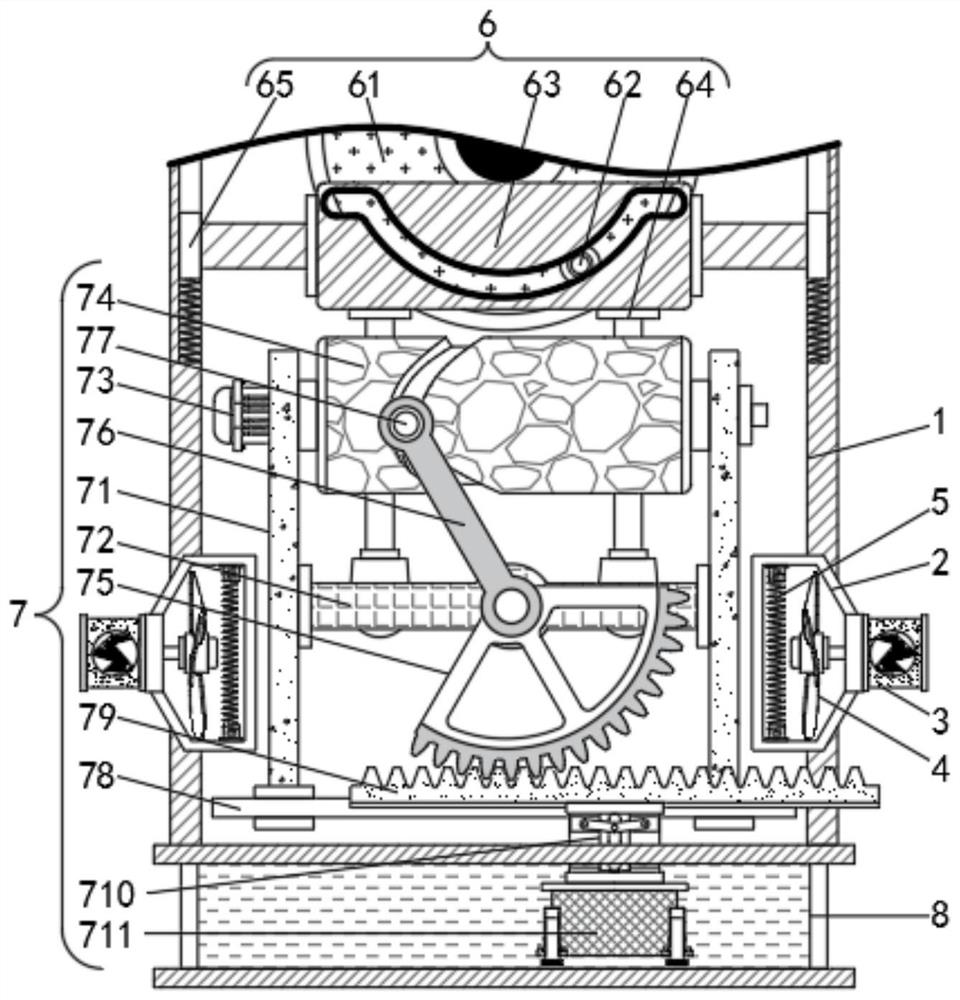
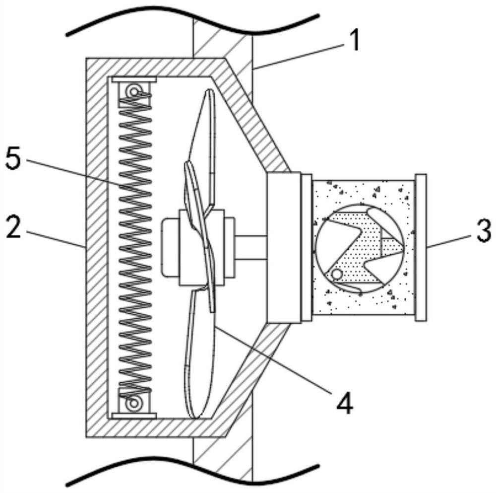
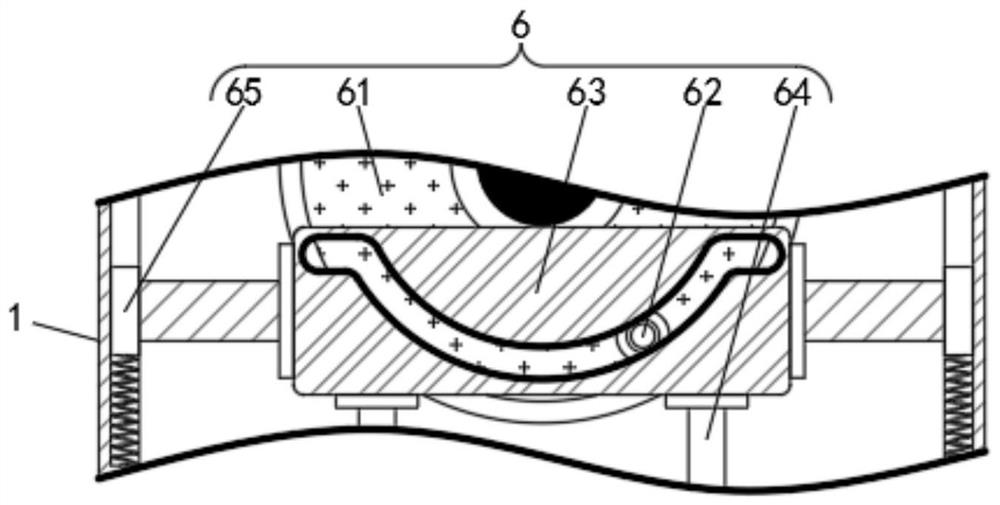
[0024] see Figure 1-3 , a high-efficiency paint dipping device for transformer windings, comprising a device main body 1, an air diffuser cover 2 is arranged on both sides of the device main body 1, a first motor 3 is fixedly connected to the outer end of the device main body 1, and the rotating shaft of the first motor 3 The fan blade 4 is fixedly connected to the top, and the inner side of the fan blade 4 is provided with a heating wire 5. The upper end of the equipment body 1 is provided with a lifting mechanism 6. The lifting mechanism 6 includes a driving disc 61, and the front end of the driving disc 61 is fixedly connected with a cylindrical pin 62. The outside of the cylindrical pin 62 is movably connected with a lifting plate 63, and the rear end of the drive plate 61 is fixedly connected with an output motor. The inside of the lifting plate 63 is provided with an arc-shaped groove, and the radius of the arc-shaped groove is the same as the radius of the circular movi...

Embodiment 2

[0026] see Figure 1-2 and Figure 4 , a high-efficiency paint dipping device for transformer windings, comprising a device main body 1, an air diffuser cover 2 is arranged on both sides of the device main body 1, a first motor 3 is fixedly connected to the outer end of the device main body 1, and the rotating shaft of the first motor 3 The fan blade 4 is fixedly connected to the top, and the inner side of the fan blade 4 is provided with a heating wire 5. The upper end of the equipment body 1 is provided with a lifting mechanism 6, and the lower end of the lifting mechanism 6 is provided with a paint dipping mechanism 7. The paint dipping mechanism 7 includes a fixing plate 71 , the inner side of the fixed plate 71 is fixedly connected with a support arm 72, the left end of the fixed plate 71 is fixedly connected with a second motor 73, the upper end of the support arm 72 is provided with a roller 74, and the middle part of the support arm 72 is movably connected with a secto...

Embodiment 3

[0028] see Figure 1-4 , a high-efficiency paint dipping device for transformer windings, comprising a device main body 1, an air diffuser cover 2 is arranged on both sides of the device main body 1, a first motor 3 is fixedly connected to the outer end of the device main body 1, and the rotating shaft of the first motor 3 The fan blade 4 is fixedly connected to the top, and the inner side of the fan blade 4 is provided with a heating wire 5. The upper end of the equipment body 1 is provided with a lifting mechanism 6. The lifting mechanism 6 includes a driving disc 61, and the front end of the driving disc 61 is fixedly connected with a cylindrical pin 62. The outside of the cylindrical pin 62 is movably connected with a lifting plate 63, and the rear end of the drive plate 61 is fixedly connected with an output motor. The inside of the lifting plate 63 is provided with an arc-shaped groove, and the radius of the arc-shaped groove is the same as the radius of the circular movi...


PUM


Abstract

The invention relates to the technical field of transformers, and discloses an efficient paint dipping device for a transformer winding. The efficient paint dipping device comprises an equipment body, the two sides of the equipment body are provided with air expanding covers, the outer ends of the air expanding covers are fixedly connected with first motors, rotating shafts of the first motors are fixedly connected with fan blades, and the inner sides of the fan blades are provided with electric heating wires; a lifting mechanism is arranged at the upper end of the equipment body, a paint dipping mechanism is arranged at the lower end of the lifting mechanism, and a paint dipping chamber is arranged on the lower portion of the equipment body. According to the efficient paint dipping device for the transformer winding, a curved groove in the surface moves through rotation of a roller, a limiting block moves in the curved groove, the limiting block drives a sector gear to swing through a connecting rod, the sector gear moves a rack plate to move, and the rack plate moves to drive a placing frame to shake left and right, therefore, the transformer electric winding in the placing frame is more fully dipped in the paint liquid, the paint dipping speed is improved, and the time of the paint dipping process is shortened.

Description

technical field [0001] The invention relates to the technical field of transformers, in particular to a high-efficiency paint dipping device for transformer windings. Background technique [0002] In order to ensure the development of modern industry and the electricity consumption of residents, a large number of power facilities have been built. In order to ensure the wired transmission of electricity, high-voltage transmission is often used during power transmission, and then the voltage is changed through transformers for power supply. During the manufacturing process of the transformer, its windings need to be dipped in varnish, and all space air gaps are filled with insulating varnish, so that the insulation strength and moisture-proof strength of the windings can be improved, and the heat resistance and heat dissipation of the windings can also be improved. The existing Most of the dipping methods are to soak the transformer windings in the paint solution. This method ...

Claims


Application Information

Patent Timeline
Patent Type & Authority Applications(China)
IPC IPC(8): H01F41/12F26B5/08F26B21/00
CPCH01F41/127H01F41/12F26B5/08F26B21/001F26B21/004
Inventor 王吉志
Owner 江苏士丰电气有限公司
Why Eureka
Try Eureka