
Eureka
For R&D, Eureka makes reading and utilizing patents & technical documents easy.
Eureka AIR
Designed for self-driven R&D workflows. Generate viable solutions, solve complex R&D challenges, empower your innovation with AI.

Eureka Materials
Designed for material experts only. Revolutionize your material R&D, from search, analyze, to developing new materials.

TechResearch
Generate reliable direction feasibility study reports for your R&D in just a few steps.

TechSeek
Discover and master advanced knowledge NOW. Basics, ideas, possibilities, all at once.

TechMind
As an expert in R&D Theories, TechMind can generates customized viable solutions instantly.

TechRisk
Analyze your overall solution with one click, know your potential R&D risks in advance.

TechMonitor
Get weekly tech updates, stay abreast of the latest tech innovations and key insights.
New energy battery device
A battery device and battery protection device technology, which is applied to battery components, circuits, electrical components, etc., can solve problems such as liquid leakage, low protection efficiency, and inability to protect the battery from shocks from all directions, so as to achieve convenient use and increase The effect of conservation efficiency
- Summary
- Abstract
- Description
- Claims
- Application Information
AI Technical Summary
Problems solved by technology
Method used
Image

Examples
Embodiment 1
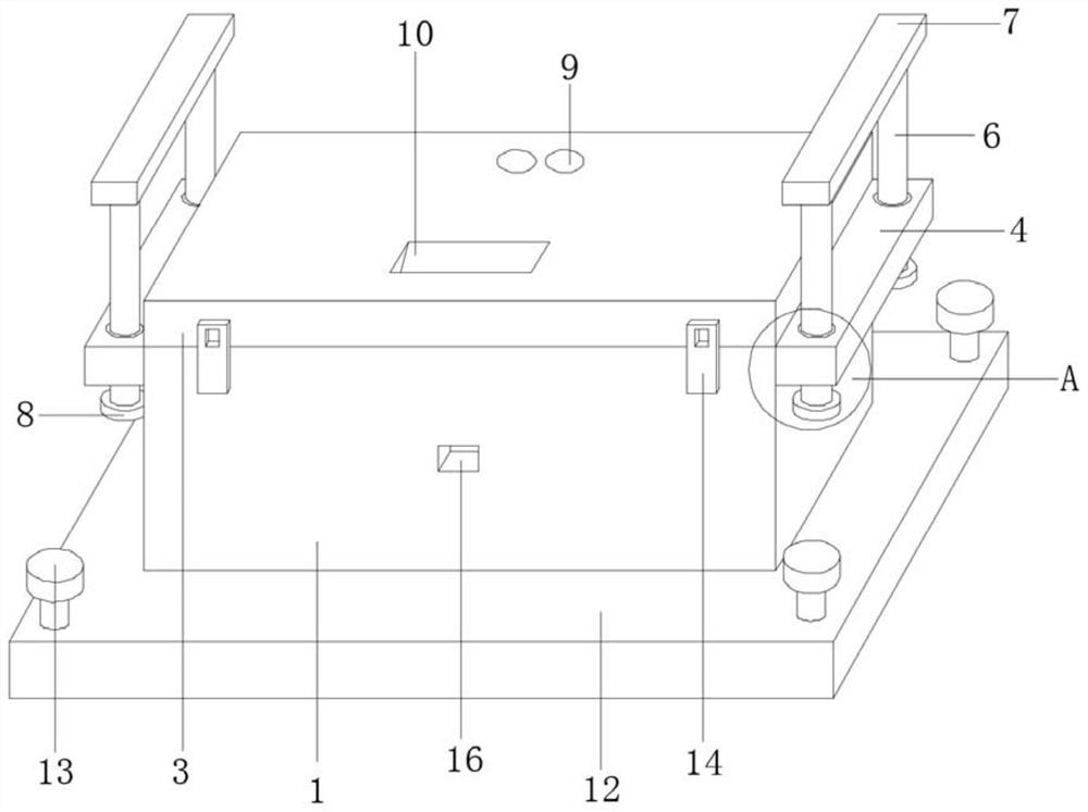
[0035] refer to figure 1 , a new energy battery device provided by the present invention includes a housing 1, the upper rear end of the housing 1 is connected to a cover 3 through a hinge 2, the cover 3 can protect the top of the new energy battery 19, the upper parts of the left and right ends of the housing 1 are The support block 4 is fixedly connected, and the support block 4 can support the equipment during transportation. The front and rear parts of the support block 4 are provided with openings 5, and the inside of the opening 5 is slidingly connected with a tie rod 6, which can be stretched. The bottom end of the horizontal bar 7 and the cover 3 is fixedly connected with a shock absorber 11, which can absorb the impact force from the top of the new energy battery 19, and the middle part of the inner wall of the front end of the housing 1 is fixedly connected with a charger 15, and the charger 15 can To charge the new energy battery 19, support columns 18 are evenly di...
Embodiment 2
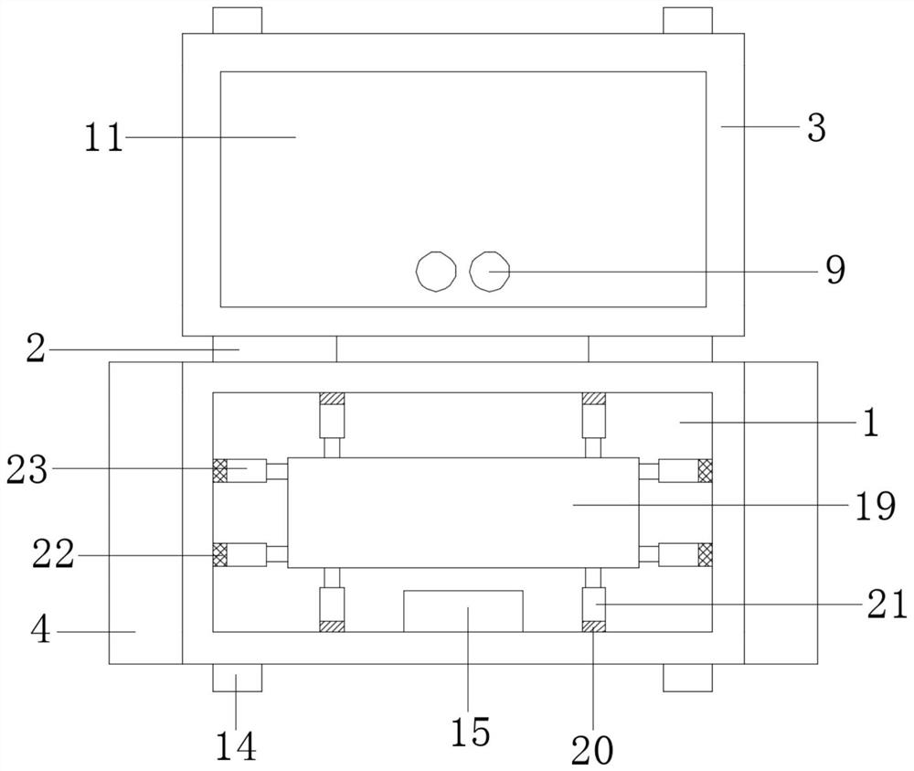
[0037] In this embodiment: the interior of the casing 1 and the cover 3 is filled with non-Newtonian fluid 17, which can increase the ability of the casing 1 and the cover 3 to resist impact force, and the top of the tie rod 6 is fixedly connected with a cross bar 7, which The rod 7 can move the equipment conveniently. The bottom end of the pull rod 6 is fixedly connected with the limit block 8. The limit block 8 can prevent the pull rod 6 from falling off. The cross bar 7, the pull rod 6 and the limit block 8 can facilitate the handling of the equipment. The cover 3 and the rear portion of the damping block 11 are provided with threading holes 9, through which the wires can be arranged, and the top front of the cover 3 is provided with a grip groove 10, which can facilitate the opening and closing of the lid 3 through the grip groove 10. The bottom end is fixedly connected with a base 12, and the four corners of the top of the base 12 are screwed with fixing screws 13. The equ...
Embodiment 3
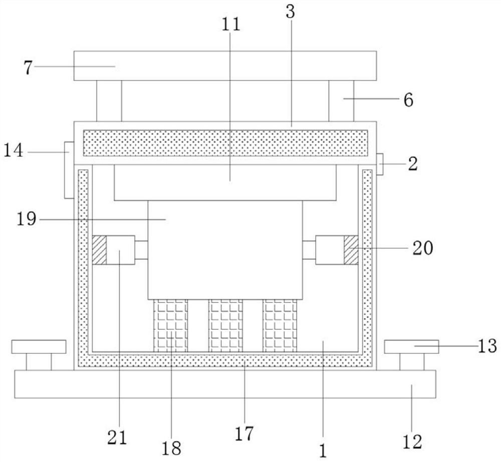
[0039] In this embodiment: refer to Figure 2-3 ,from figure 2 and Figure three Be able to show how the device absorbs impact forces from all directions. refer to Figure 4 , The new energy battery protection device provided by the present invention adopts the shock absorbing block 11 made of foam material and the support column 18 made of silica gel to absorb the impact from above and below the new energy battery 19 .
[0040]The left and right sides of the upper front end of the housing 1 and the left and right sides of the front end of the cover 3 are fixedly connected with buckles 14, the middle of the front end of the housing 1 is provided with a charging port 16, the charger 15 is electrically connected to a new energy battery 19, and a shock absorber 11 The material of the support column 18 is foam, the material of the support column 18 is silica gel, the front end and the rear end of the new energy battery 19 are fixedly connected to the other end of the first dam...
PUM
 Abstract
Description
Claims
Application Information
 - R&D Engineer
- R&D Manager
- IP Professional
- Industry Leading Data Capabilities
- Powerful AI technology
- Patent DNA Extraction
Browse by: Latest US Patents, China's latest patents, Technical Efficacy Thesaurus, Application Domain, Technology Topic, Popular Technical Reports.
© 2024 PatSnap. All rights reserved.Legal|Privacy policy|Modern Slavery Act Transparency Statement|Sitemap|About US| Contact US: help@patsnap.com