Supercharge Your Innovation With Domain-Expert AI Agents!

Oil cylinder rod head machining clamp with bottom supported in suspended mode

A cylinder rod and fixture technology, applied in the field of cylinder rod head processing fixtures, can solve problems such as troublesome and unsupported overturning, and achieve the effect of reducing the operation process, improving the processing accuracy, and having a good fixing effect.

Inactive Publication Date: 2022-01-04
CHANGDE JIAHONG MACHINERY
View PDF10 Cites 0 Cited by
  • Summary
  • Abstract
  • Description
  • Claims
  • Application Information

AI Technical Summary

Problems solved by technology

[0003] The object of the present invention is to provide a jig for processing a cylinder rod head supported by a suspended bottom, to solve the problem that the existing cylinder rod head clamp proposed in the above-mentioned background technology includes a rotatable clamp, and the surface of the cylinder rod head can be adjusted by rotation. In this way, multiple end faces can be processed in one clamping, but this method does not support flipping. Generally speaking, only three faces can be processed except the fixed faces on both sides. In this case, additional drilling is required when drilling the bottom face. One-time clamping operation, more troublesome problem

Method used


Image

  • Oil cylinder rod head machining clamp with bottom supported in suspended mode
  • Oil cylinder rod head machining clamp with bottom supported in suspended mode
  • Oil cylinder rod head machining clamp with bottom supported in suspended mode

Examples


Embodiment 1

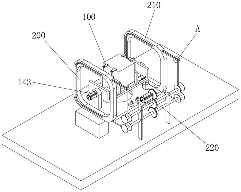
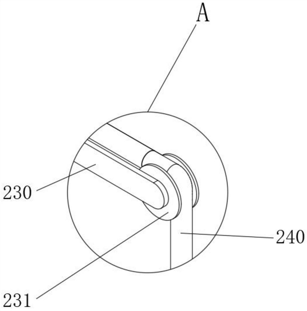
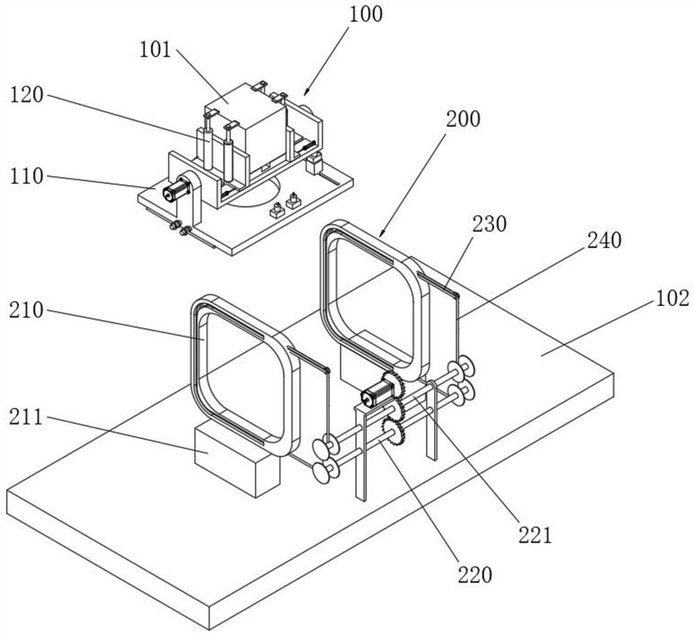
[0049] See Figure 1 - Figure 10 , The cylinder head is provided with a jig machining the bottom of truss-supported, 200, the clamping device comprises a clamping means 100 and the turnover device 100 is mounted on the fixture 100 includes at least:

[0050] Web 140, web 140 defines a circular hole 145 at the center, the connecting plate 140 is provided above the fixing plate 130, post 135 is provided below the stationary transfer plate 130, in turn connected to post 135 rotates the circular hole 145, 130 above the fixed plate Shen defines a groove 131, a base for receiving the cylinder head, the sink 132 defines a plurality of grooves 131 machined hole, for guiding a drill bit;

[0051] Clamp 120, clamp 120 is provided below the slider 124, the upper connecting plate 140 defines a sliding groove 141, the slide block 124 is slidably connected within the sliding groove 141, rotating cylinder 120 is provided with side clamp 121, preferably a high-pressure type, to enhance the accurac...


PUM


Abstract

The invention relates to the technical field of oil cylinder rod head clamps, and particularly relates to an oil cylinder rod head machining clamp with the bottom supported in a suspended mode. The clamp comprises a supporting plate, a penetrating hole is formed in the center of the supporting plate, lug plates are arranged at two sides of the supporting plate, rotating shafts are arranged at two sides of a connecting plate, the rotating shafts are rotatably connected to the lug plates, first motors are arranged outside the lug plates, the first motors are coaxially connected with the rotating shafts, guiding grooves are formed in annular blocks and are of a U-shaped structure, a bottom plate is arranged below the supporting plate, the guide grooves are formed in the upper portion of the bottom plate, the annular blocks are fixed to the guide grooves, a plurality of sliding rods are symmetrically arranged on the side surface of the supporting plate, and the sliding rods are connected into the guide grooves in a sliding mode. According to the clamp, overturning is completed through movement of the supporting plate along the guide grooves, the front surface a workpiece faces downwards, the backside of the workpiece faces upwards, a drill bit can machine the workpiece through a penetrating hole, a round hole and a machining hole, and the number of the end surfaces which can be machined through one-time clamping is increased to four.

Description

Technical field [0001] The present invention relates to a cylinder head clamp Field, in particular, to a bottom of the cylinder head of truss-supported processing jig. Background technique [0002] Cylinder head drilling process scheme, NC four-jaw chuck holding a workpiece, using a center positioned end surface to be fixed by bonding four four faces of the cylinder head, in the course of processing a surface of each of need to re-setup time, extremely troublesome, the conventional cylinder head includes a rotatable jig fixture, a fixture can be processed by a plurality of end faces of the cylinder head is rotated toward the surface control, but this approach does not support rollover Generally only process three sides except the sides of the fixing surface, requires additional setup operation once, when the bottom surface of the borehole is troublesome in this case, in view of this, the present invention proposes a floating bottom the cylinder head machining type support jig. I...

Claims


Application Information

Patent Timeline
Patent Type & Authority Applications(China)
IPC IPC(8): B23Q3/06B23Q7/00B23B47/28
CPCB23Q3/062B23Q7/00B23B47/28
Inventor 谭宇岐铁钟杨龙
Owner CHANGDE JIAHONG MACHINERY
Features
  • R&D
  • Intellectual Property
  • Life Sciences
  • Materials
  • Tech Scout
  • Unparalleled Data Quality
  • Higher Quality Content
  • 60% Fewer Hallucinations
Learn More