Vertical take-off and landing and fixed wing hovercars

A flying car and vertical take-off and landing technology, applied to vertical take-off and landing aircraft, aircraft, vehicles that can be converted into airplanes, etc., can solve problems such as blade tip shock wave vibration, easy yaw when wind blows, flight instability, etc. , to achieve the effect of maintaining flight stability, taking into account vertical take-off and landing, and reducing the workload

Pending Publication Date: 2022-01-04
张锐
View PDF0 Cites 1 Cited by
  • Summary
  • Abstract
  • Description
  • Claims
  • Application Information

AI Technical Summary

Problems solved by technology

[0004] If a new flying car adopts a general bladed propeller lift unit, in order to ensure high endurance, it is necessary to stop the bladed propeller. At this time, the stationary bladed propeller will face the impact of the airflow during high-speed flat flight, resulting in turbulent flow, resulting in unstable flight. In addition, when the flying car is flying at high speed and level, the windward or crosswind laminar flow will also directly impact the blades, and the tip of the blades will also produce shock wave vibration, and it is easy to fly unstable; and there is also a large wind resistance , The problem of wind blowing and easy yaw when hovering; therefore, the flying car needs to adopt a new structural scheme on the vertical lift unit to adapt to the high-speed laminar flow in the level flight process, and it can also decompose the flight motion control from the control level relatively simply Acceleration and deceleration control for vertical take-off and landing control and level flight, in order to realize vertical take-off and landing, fixed-wing level flight, land acceleration and deceleration and landing driving

Method used


Image

  • Vertical take-off and landing and fixed wing hovercars
  • Vertical take-off and landing and fixed wing hovercars
  • Vertical take-off and landing and fixed wing hovercars

Examples


Embodiment Construction

[0063] The embodiments of the present invention will be further described below in conjunction with the accompanying drawings.

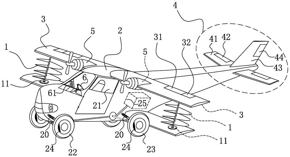
[0064] figure 1 It is embodiment 1 of vertical take-off and landing and fixed-wing flying vehicle of the present invention. It is adapted to use the engine to provide all driving power. As shown in the figure, the flap 31 is arranged on the rear edge of the main wing 3 near the position of the vehicle body 2, and the aileron 32 is arranged on the rear edge of the main wing 3 away from the position of the vehicle body 2; the elevator 42 is arranged on the rear edge of the horizontal tail 41, The rudder 44 is arranged on the rear edge of the vertical tail 43; the multi-layer continuous airfoil propeller 1 is a multi-layer continuous spiral airfoil structure, which is connected and driven to rotate by the power unit 11; the root of the main wing 3 is fixed on both sides of the vehicle body 2; The empennage 4 is fixed on the tail of the vehicle body 2;...


PUM


Abstract

The invention provides two manned vertical take-off and landing and fixed-wing hovercars and two vertical take-off and landing and fixed-wing hovercars with manned and wireless remote control functions. A multi-layer continuous airfoil propeller is adopted to provide lifting force in the vertical direction, and the spiral airfoil structure of the multi-layer continuous airfoil propeller is utilized to cut and adapt to windward rapid laminar flow or crosswind laminar flow, so that the phenomena that the windward laminar flow or the crosswind laminar flow directly generates airflow impact on the blades and the wingtips of the blades generate shock wave vibration when a common blade type propeller is adopted, resulting in large wind resistance, unstable flight or hovering and yawing caused by wind blowing are avoided; a flight driving device is adopted to provide level flight power after lift-off, and during rapid level flight, after operation of a multi-layer continuous airfoil propeller is stopped, lift force is generated by a main wing to maintain level flight, so that fuel or electric power is saved, and the endurance time is prolonged; the attitude of each hovercar is adjusted by wing control surface actions, so that the flight control difficulty is reduced; the combined take-off and landing modes such as vertical take-off and landing and gliding take-off and landing can be achieved, and the adaptability to take-off and landing sites is improved.

Description

technical field [0001] The invention relates to the field of vehicles and flying cars, in particular to two types of manned vertical take-off and landing and fixed-wing flying cars and two types of vertical take-off and landing and fixed-wing flying cars with both manned and wireless remote control functions. Background technique [0002] With the development of science and technology, cars have become the main means of transportation for people's daily travel, and traffic jams during rush hours have become a common problem. Therefore, the flying car was born, which can become an ideal means of transportation. When it is congested on the surface, it can be converted to flight mode to realize travel. Most of the current flying cars are multi-rotor flying cars and fixed-wing flying cars. Among them, the multi-rotor flying car still needs multi-rotor rotation to maintain after it is lifted into the air, so it is not conducive to improving the air endurance time of the flying c...

Claims


Application Information

Patent Timeline
Patent Type & Authority Applications(China)
IPC IPC(8): B60F5/02B64C27/22B64C27/26B64C27/32B64C25/44B64D43/00B64C29/00
CPCB60F5/02B64C27/22B64C27/26B64C27/32B64C25/44B64D43/00B64C29/00
Inventor 张锐
Owner 张锐
Why Eureka
Try Eureka