Monorail crane rail mounting vehicle

A monorail crane and installation vehicle technology, applied to vehicles with cranes, hoisting devices, transportation and packaging, etc., can solve problems such as hidden safety hazards, low installation efficiency, and no transportation function, so as to improve work efficiency and improve safety. , the effect of reducing labor intensity

Pending Publication Date: 2022-01-04
JIKAI HEBEI MECHATRONICS TECH CO LTD
View PDF0 Cites 0 Cited by
  • Summary
  • Abstract
  • Description
  • Claims
  • Application Information

AI Technical Summary

Problems solved by technology

[0002] There is a lot of track installation work in the application of monorail cranes in coal mines. The rails need to be installed from the ground to the top of the roadway, and each adjacent guide rail is fixed by concave-convex buckles. At this stage, the installation method of monorail crane rails is generally manual installation. The shift requires 4-5 workers to operate at the same time, and it is equipped with lifting hoists, escalators and other equipment. There are problems of labor intensity and low efficiency of workers, and there are safety hazards at the same time. In addition, there are mechanized installation equipment on the market now. Pick it up, lift the guide rail to the top of the roadway through the lifting of the mechanical arm, and then perform manual assisted installation. At the same time, the track needs to be placed in a fixed position on the roadway ground in advance, and the tight installation of the concave-convex buckles of the adjacent rails cannot be achieved. It is inefficient and has no transport function, for which we propose a monorail crane track mounted vehicle

Method used


Image

  • Monorail crane rail mounting vehicle
  • Monorail crane rail mounting vehicle

Examples


Embodiment Construction

[0016] In order to make the technical means, creative features, goals and effects achieved by the present invention easy to understand, the present invention will be further described below in conjunction with specific embodiments.

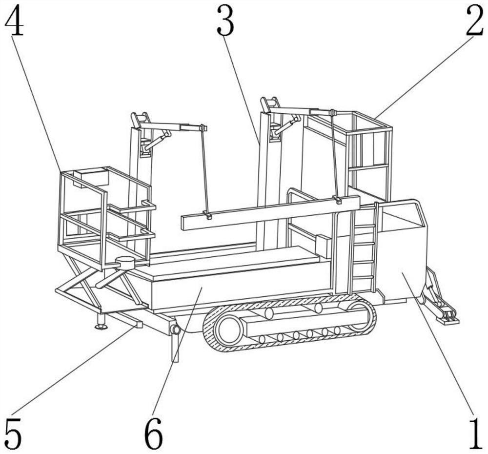
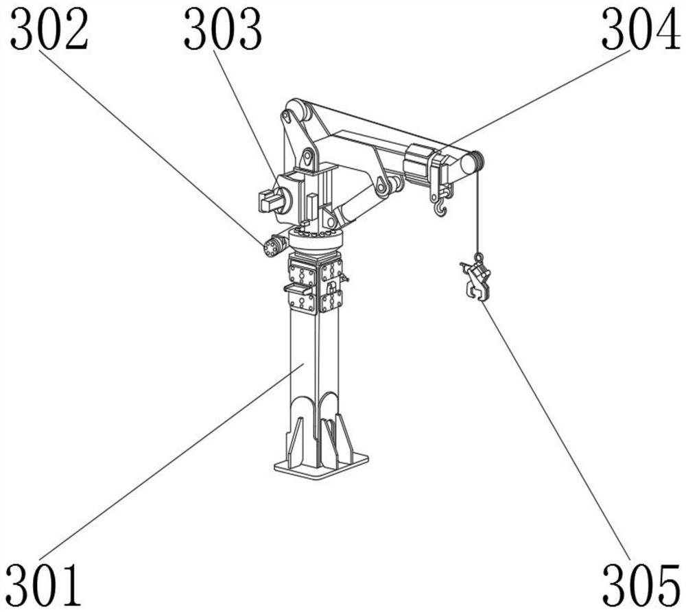
[0017] like Figure 1-2 As shown, the monorail crane track installation vehicle includes a nose 1, a transport mechanism 6 is arranged on the outer surface of one end of the nose 1, a front platform 2 is arranged on one side outer surface of the transport mechanism 6, and a front platform 2 is arranged on the other side outer surface of the transport mechanism 6. A rear platform 4 is provided, a vehicle stabilizing mechanism 5 is provided on the outer surface of the lower end of the transport mechanism 6, and a lifting arm 3 is provided on the outer surface of the upper end of the transport mechanism 6. The lifting arm 3 includes a boom 301, an angle adjustment device 302, a lifting device 303, The forearm 304, the snatch device 305, the angle adj...


PUM


Abstract

The invention discloses a monorail crane rail mounting vehicle, and relates to the field of monorail crane rail mounting. The monorail crane rail mounting vehicle comprises a machine head, a transportation mechanism is arranged on the outer surface of one end of the machine head, a front platform is arranged on the outer surface of one side of the transportation mechanism, and a rear platform is arranged on the outer surface of the other side of the transportation mechanism; and a vehicle stabilizing mechanism is arranged on the outer surface of the lower end of the transportation mechanism, a hoisting arm is arranged on the outer surface of the upper end of the transportation mechanism, the hoisting arm comprises a large arm, an angle adjusting device, a hoisting device, a small arm and a grabbing and lifting device, and the angle adjusting device and the hoisting device are both located on the outer surface of one side of the large arm. The monorail crane rail mounting vehicle is composed of the machine head, the front platform, the hoisting arm, the rear platform, the vehicle stabilizing mechanism and the transportation mechanism, and has a transportation function, the integrated operation of guide rail transportation and installation can be achieved, the operation efficiency is improved, the labor intensity of workers is reduced, the operation safety is improved, and the monorail crane rail mounting vehicle is better in use effect compared with a traditional mode.

Description

technical field [0001] The invention relates to the field of monorail crane track installation, in particular to a monorail crane track installation vehicle. Background technique [0002] There is a lot of track installation work in the application of monorail cranes in coal mines. The rails need to be installed from the ground to the top of the roadway, and each adjacent guide rail is fixed by concave-convex buckles. At this stage, the installation method of monorail crane rails is generally manual installation. The shift requires 4-5 workers to operate at the same time, and it is equipped with lifting hoists, escalators and other equipment. There are problems of labor intensity and low efficiency of workers, and there are safety hazards at the same time. In addition, there are mechanized installation equipment on the market now. Pick it up, lift the guide rail to the top of the roadway through the lifting of the mechanical arm, and then perform manual assisted installation...

Claims


Application Information

Patent Timeline
IPC IPC(8): B66F11/04B66C23/06B66C23/44B66C23/84B66C23/78B66C1/42B60P1/54B60P3/40
CPCB66F11/04B66F11/042B66C23/06B66C23/44B66C23/84B66C23/78B66C1/42B60P1/54B60P3/40
Inventor 李立青冯帆周茂普陈浩宁刘天康栩源李哲张芝国张亮李岩
Owner JIKAI HEBEI MECHATRONICS TECH CO LTD
Why Eureka
Try Eureka