

Full-automatic plane bearing sleeving and assembling height detection machine
A flat bearing and assembly height technology, applied in the field of automatic parts assembly, can solve the problems of low fitting and measurement efficiency, many uncertain factors, poor stability of finished products, etc., to achieve high fitting efficiency, reduced labor intensity, and high degree of automation. Effect
- Summary
- Abstract
- Description
- Claims
- Application Information
AI Technical Summary
Problems solved by technology
Method used
Image

Examples
Embodiment Construction
[0041] The preferred embodiments of the present invention will be described in detail below in conjunction with the accompanying drawings, so that the advantages and features of the present invention can be more easily understood by those skilled in the art, so as to define the protection scope of the present invention more clearly.
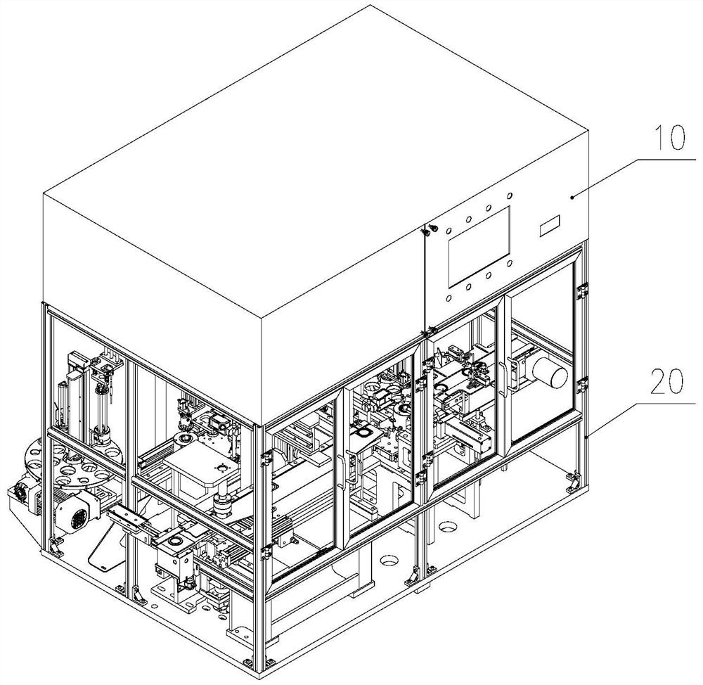
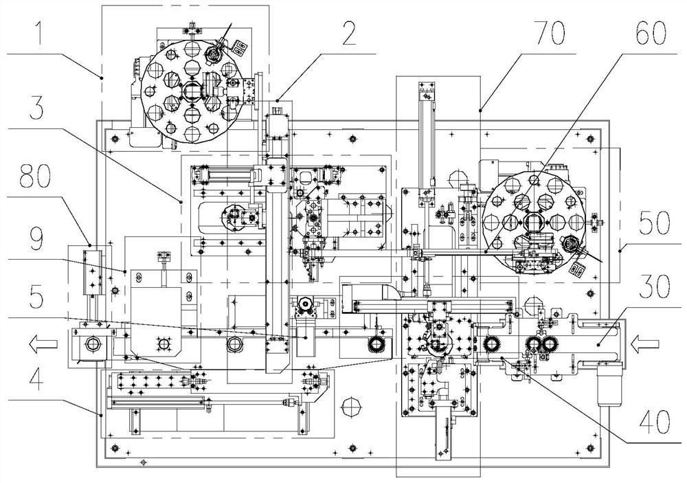
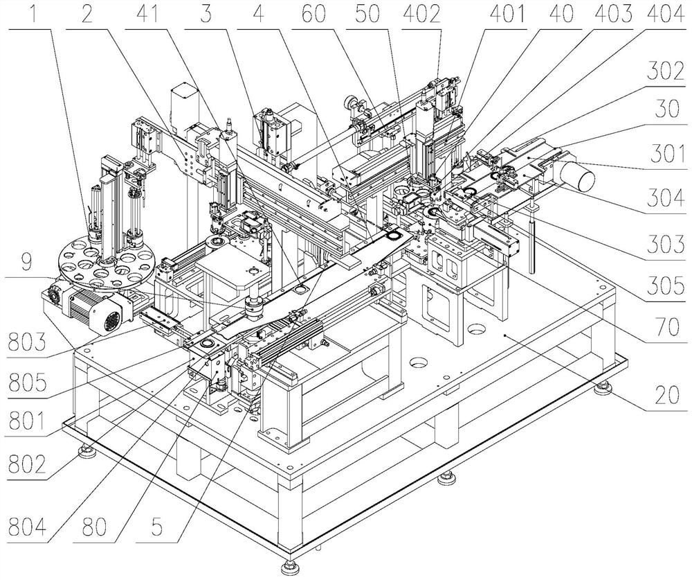
[0042] Such as Figure 1-3 A fully automatic planar bearing assembly and assembly height detection machine shown includes an electric box control device 10, a stand 20, a planar bearing feeding part 30 arranged in the stand 20, and a planar bearing loading and unloading manipulator 40 , outer thrust sheet material bin 50, outer thrust sheet feeding manipulator 60, outer thrust sheet assembly part 70, bearing assembly height measurement part 9 and NG discharge part 80, also includes inner thrust sheet material bin 1, inner thrust sheet feeding and bearing Component loading and unloading manipulator component 2 , inner thrust plate fitting part 3 , ...
PUM
 Abstract
Description
Claims
Application Information