
Energy-saving and environment-friendly LED lamp

An LED lamp, energy-saving and environment-friendly technology, applied in energy-saving lighting, outdoor lighting, photovoltaic modules, etc., can solve the problems of low conversion rate of electric energy, large solar energy reception, and much dust on the surface of solar panels, so as to prevent jamming, The effect of increasing utilization

Pending Publication Date: 2022-01-04
倪井兵
View PDF0 Cites 0 Cited by
  • Summary
  • Abstract
  • Description
  • Claims
  • Application Information

AI Technical Summary

Problems solved by technology

[0003] At present, the solar street lamps on the market usually fix the solar panels at an angle to convert the received solar energy into electric energy for the street lamps to use at night. When the sun shines directly on the solar panels, the solar energy received is large. For other angles to irradiate the solar panel, the conversion of electric energy is more. Since the angle of the solar panel is fixed, with the movement of the sun during the day, the amount of electrical energy converted by the solar panel cannot be maintained at a high level. When the solar panel is facing away from the When the sun is on, the conversion rate of electric energy will be lower, and there is too much dust on the surface of the solar panel, which will affect the efficiency of solar conversion. Therefore, there is an urgent need for a solar panel that will rotate with the sun to ensure that the amount of solar conversion is at a high level. It is an energy-saving and environmentally friendly LED lamp that can automatically clean the dust on the surface of the solar panel

Method used


Image

  • Energy-saving and environment-friendly LED lamp
  • Energy-saving and environment-friendly LED lamp
  • Energy-saving and environment-friendly LED lamp

Examples


Embodiment Construction

[0027] In order to make the technical means, creative features, goals and effects achieved by the present invention easy to understand, the present invention will be further described below in conjunction with specific embodiments.

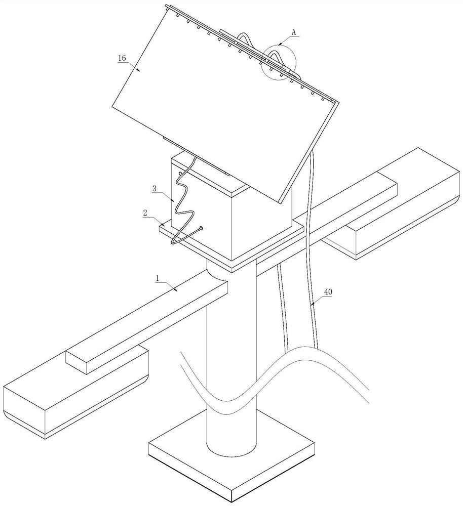
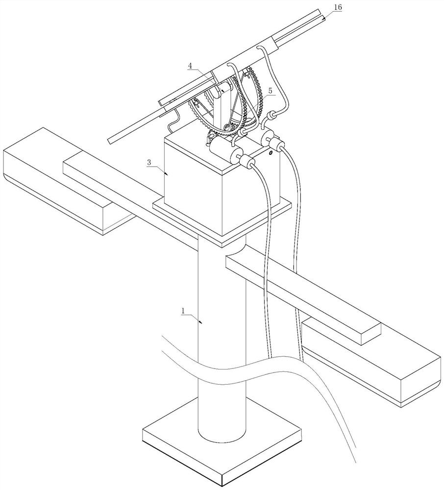
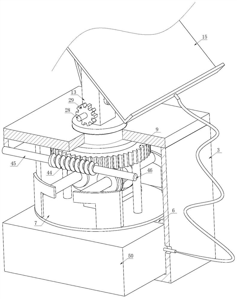
[0028] Such as Figure 1-Figure 8 As shown, an energy-saving and environment-friendly LED lamp according to the present invention includes a lamp post 1, a support plate 2 is fixedly connected to the top of the outer peripheral surface of the lamp post 1, and a box body 3 is fixedly connected to the top of the support plate 2. A calibration device 4 is provided inside the box body 3, and a cleaning device 5 is provided on the top of the box body 3. The calibration device 4 is activated once every hour to make the solar battery panel 16 rotate an angle, so that the solar battery panel 16 It is relatively perpendicular to the sunlight, increasing the area to receive solar energy, thereby increasing the amount of solar energy collected, and there wil...


PUM


Abstract

The invention relates to the technical field of LED lamps, and particularly relates to an energy-saving and environment-friendly LED lamp which comprises a lamp post. A supporting plate is fixedly connected to the top end of the peripheral surface of the lamp post, a box is fixedly connected to the top of the supporting plate, a calibration device is arranged in the box, and a cleaning device is arranged at the top of the box. The calibration device comprises a partition plate fixedly connected with the interior of the box, a supporting disc is placed on the top of the partition plate, and two symmetrically-distributed supporting cylinders are fixedly connected to the top of the supporting disc. A motor in the calibration device is started at regular time to drive the solar cell panel to rotate by 18 degrees every one hour so that the solar cell panel is relatively perpendicular to sunlight, the sunlight directly irradiates the solar cell panel at the moment, and therefore the receiving amount of solar energy is ensured to be at a high level, and the situation that the solar cell panel is back to the sun can be prevented from occurring; and the all-day utilization rate of solar energy is increased.

Description

technical field [0001] The invention relates to the technical field of LED lamps, in particular to an energy-saving and environment-friendly LED lamp. Background technique [0002] The light-emitting diode lamps used in LED lamps are becoming the main product in the new generation of lighting market due to their technical characteristics of high efficiency, energy saving, safety, longevity, compactness, and clear light, and they are powerfully driving the rapid development of the environmental protection and energy-saving industry. Because LED lights have the characteristics of low energy consumption and good lighting effect, they are mostly used in urban lighting systems. They are usually used in conjunction with solar panels and energy storage devices that must be equipped to convert solar energy into electrical energy during the day. It can be used for road lighting at night, thus saving electricity in the city. [0003] At present, the solar street lamps on the market u...

Claims


Application Information

Patent Timeline
Patent Type & Authority Applications(China)
IPC IPC(8): F21S9/03H02S20/32H02S40/10B08B3/02F21W131/103F21Y115/10
CPCF21S9/035H02S20/32H02S40/10B08B3/02F21W2131/103F21Y2115/10Y02E10/50Y02B20/72
Inventor 倪井兵秦本兵
Owner 倪井兵
Learn More