Depth-adjustable portable soil collection drilling equipment
A drilling equipment and portable technology, applied in the field of portable soil collection drilling equipment, can solve the problems of difficult soil research, inconvenient operation, poor portability, etc., and achieve the effects of convenient soil collection, improved stability, and convenient operation
- Summary
- Abstract
- Description
- Claims
- Application Information
AI Technical Summary
Problems solved by technology
Method used
Image
Examples
Embodiment 1
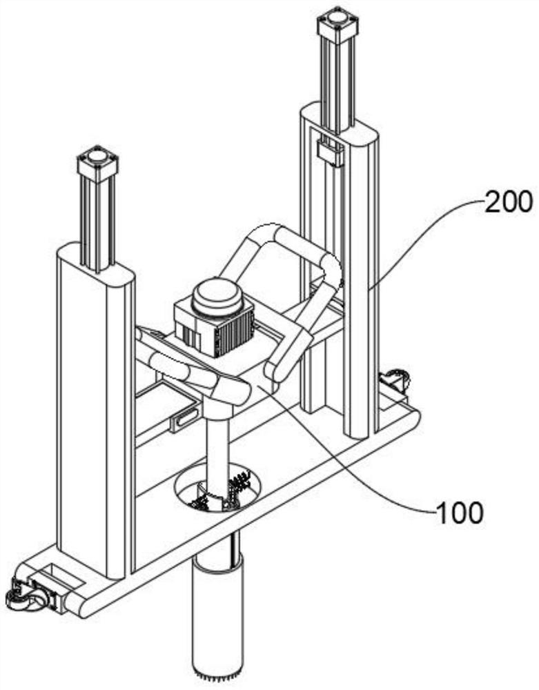
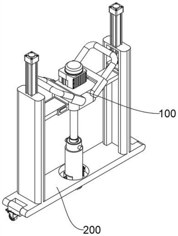
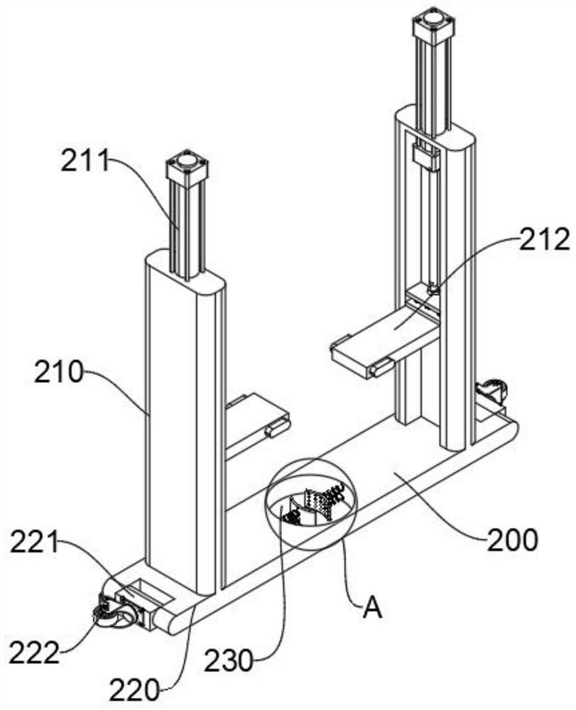
[0047] See Figure 1 - Figure 8 , The present embodiment provides a portable form a deep soil collection adjustable drilling equipment, comprising at least:
[0048] Holder 100, a rotary bracket 100 fixed to the top of the motor 110, rotation motor 110 is rotated through the output end surface of the holder 100, and is locked to a connecting rod 111 fixed to the connecting rod 111 is provided with an end portion of the drill pipe 120, it may be in use, the rotation of the motor 110 is powered, to make it work, driven by the rotating output shaft of the motor 110 rotates the connecting rod 111, so as to drive rotation of the drill pipe 120 extends into the soil, the soil collected in the interior of the drill pipe 120, in order to achieve soil collection, to facilitate follow-up study, the fixed cylinder 120 includes a rod 121, the fixed cylinder 121 fixed to an end portion of the connecting rod 111, an outer wall of the fixed cylinder 121 defines two symmetrical adjustment groove 1...
Embodiment 2
[0063] In order to facilitate removal installation holder 100 and connecting rod 111, to facilitate the subsequent maintenance and replacement, according to the present embodiment and the embodiment is different from 1, see Figure 9 - Figure 11 Shown, wherein:
[0064] Near both ends of the connection rod 111 has a snap coupling sleeve 1114, two side portions connecting sleeve 1114 is fixed to the bottom bracket tube 100 and the fixed end portion 121, an outer wall connecting sleeve 1114 defines a slot 1115.
[0065] To facilitate removal installation connecting rod 111, near the end of each connecting rod 111 defines a sliding groove 1111, the chute 1111 internal slide card has a column 1112, an end portion of the card between the column 1112 and a lumen 1111 chute end portion fixedly connected detent spring 1113, a column 1112 and the card slot 1115 adapted to be mounted upon the connecting rod 111, are respectively pressed against the internal slide card column 1112 chute 1111,...
Embodiment 3
[0068] In order to ensure that the drill pipe 120 can move horizontally, avoid the offset affecting the soil collection quality, this example is different from the first embodiment, please refer to Figure 12 - Figure 13 Disted, where:
[0069] There is a restricted groove 230 at the bottom of the support frame 200, and two symmetrical limit arc plates 231 are provided inside the restricted groove 230, and the external wall of the limit arc plate 231 and the inner wall of the limit groove 230 is compressed, which can be made The drill pipe 120 drills the soil from the limit slot 230, and the drill pipe 120 is located between the two limit arc plates 231, and the two limit arc plate 231 The outer wall of the gripper rod 120 is gathered to ensure that the drill rod 120 can move horizontally to avoid offset, affecting the quality of soil collection.
[0070] In order to reduce the frictional resistance between the limit arc plate 231 and the outer wall of the drill rod 120, the surfac...
PUM
 Abstract
Description
Claims
Application Information
 - R&D
- Intellectual Property
- Life Sciences
- Materials
- Tech Scout
- Unparalleled Data Quality
- Higher Quality Content
- 60% Fewer Hallucinations
Browse by: Latest US Patents, China's latest patents, Technical Efficacy Thesaurus, Application Domain, Technology Topic, Popular Technical Reports.
© 2025 PatSnap. All rights reserved.Legal|Privacy policy|Modern Slavery Act Transparency Statement|Sitemap|About US| Contact US: help@patsnap.com


