Punching device for long-life precision mold manufacturing

A technology of precision molds and punching equipment, which is applied in metal processing, dispersed particle separation, chemical instruments and methods, etc., can solve the problems of inconvenient adjustment of the depth of punching, poor applicability, etc. The effect of strong practicality and applicability

Inactive Publication Date: 2021-03-12
新昌县镇辉机械厂
View PDF7 Cites 2 Cited by
  • Summary
  • Abstract
  • Description
  • Claims
  • Application Information

AI Technical Summary

Problems solved by technology

[0009] The purpose of the present invention is to provide a long-life precision mold manufacturing punching equipment to solve t...

Method used


Image

  • Punching device for long-life precision mold manufacturing
  • Punching device for long-life precision mold manufacturing
  • Punching device for long-life precision mold manufacturing

Examples


Embodiment 1

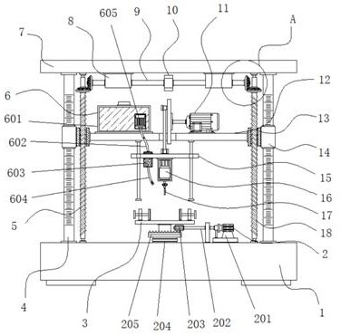
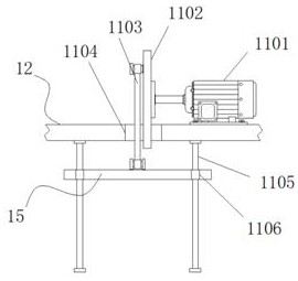
[0035]Example 1: SeeFigure 1-6, A hole in a long life precision mold, including a base 1 and a table 3, and a table 3 is disposed at the intermediate position at the top of the base 1, and the top end of the table 3 is provided with facilitating structural 21, the workbench 3 A automatic rotating mechanism 2 is provided between the bottom end and the top end of the base 1, and both sides of the top end of the base 1 are respectively fixed, and the support column 4 is fixed, respectively, and the front end of the support column 4 is provided with a scale label, and the top end of the support column 4 is fixedly connected to the top plate. 7. A cross plate 12 is provided between the support columns 4, and the bottom end of the cross plate 12 is provided with a fixing plate 15. The bottom end of the fixing plate 15 is fixedly connected to the drive motor 16, and the model number of the drive motor 16 can be Y80M2-2, drive The output of the motor 16 is fixedly connected to the drill bit...

Embodiment 2

[0040]Example 2: The automatic rotating mechanism 2 consists of a stepper motor 201, a rotating shaft 202, a pinion 203, a movable shaft 204, and a large gear 205, and the bottom end of the movable shaft 204 is fixed to the top end of the base 1, and the top end of the movable shaft 204 is fixed Connected to a large gear 205, the step motor 201 is fixed to one side of the top end of the base 1, and the model number of the step motor 201 can be XC866, and the output end of the step motor 201 is fixedly connected to the shaft 202, and the rotating shaft 202 is fixedly connected. There is a pinion gear 203, and the top end of the large gear 205 is fixed to the bottom end of the table 3;

[0041]The pinion gear 203 is engaged between the large gear 205, and the pinion 203 is in the same vertical surface on one side of the large gear 205;

[0042]Specifically, such asfigure 1 withFigure 6 As shown, in use, the step motor 201, the step motor 201 drives the shaft 202, and the rotating shaft 202 ...

Embodiment 3

[0043]Example 3: The dust collecting mechanism 6 is composed of a water tank 601, a hose 602, a nebulator 603, a spray head 604, and a water pump 605, and the water tank 601 is fixedly attached to one side of the top end of the cross plate 12, and a water pump is fixed to one side of the front end of the water tank 601. 605. The model number of the water pump 605 can be 350qz-50, and the output of the water pump 605 is fixedly connected to the hose 602, and the atomizer 603 is fixedly attached to the inside of the fixed plate 15 side, and the bottom end of the atomizer 60 is fixedly connected to nozzle. 604;

[0044]Specifically, such asfigure 1 As shown, in use, the water pump 605 is activated, and the water pump 605 can extract the water inside the water tank 601 and supplied to the nebulizer 603 by the hose 602, and the atomizer 603 is ejected by the spray head 604, so that The driver motor 16 boosted the dust generated in the process of high-speed rotation of the drill bit 17 and t...


PUM


Abstract

The invention discloses a punching device for long-life precision mold manufacturing, and particularly relates to the technical field of precision mold manufacturing equipment. The punching device comprises a base and a workbench, wherein the workbench is arranged at the middle position of the top end of the base; a structure convenient to fix is arranged at the top end of the workbench; an automatic rotating mechanism is arranged between the bottom end of the workbench and the top end of the base; supporting columns are fixedly connected to the two sides of the top end of the base respectively; and scale marks are arranged at the front ends of the supporting columns. According to the punching device, a water tank, a hose, an atomizer, a spray head and a water pump are arranged, when the punching device is used, the water pump is started, the water pump can pump out water in the water tank and supply the water to the atomizer through the hose, the atomizer can atomize the water and then spray the water out through the spray head, so that dust generated in the process that a driving motor drives a drill bit to rotate at a high speed for punching is combined with the sprayed water mist, then the dust can fall off, the dust is prevented from being diffused into the air, and the atmospheric environment is protected.

Description

Technical field[0001]The present invention relates to the technical field of precision mold manufacturing apparatus, and is specifically a punching device manufactured for long life precision molds.Background technique[0002]With the continuous development and advancement of technology, the design and manufacturing of the mold gradually towed precision, and the precision mold needs to be punched in the manufacturing process, so as to assemble the precision mold, therefore need to use a long life precision mold manufacturing. Pooffging equipment, existing long life precision mold manufacturing punk devices have many problems and defects, so they need to be improved.[0003]In the process of implementing the invention, the inventors have found that there is at least the following problems in the prior art without being resolved:[0004](1) Traditional long life precision mold manufacturing punching equipment is not convenient to adjust the depth of the punch, and the applicability is poor;...

Claims


Application Information

Patent Timeline
IPC IPC(8): B26F1/16B26D7/20B01D47/06B26D7/02B26D7/26B26D7/06
CPCB26F1/16B26D7/20B01D47/06B26D7/02B26D7/2628B26D7/0625
Inventor 周兰兰周鑫锋章德昌
Owner 新昌县镇辉机械厂
Why Eureka
Try Eureka