Eureka AIR delivers breakthrough ideas for toughest innovation challenges, trusted by R&D personnel around the world.

Scanning device for laser radar, control method of scanning device and laser radar

A technology of scanning device and laser radar, which is applied in the direction of measuring device, utilization of re-radiation, re-radiation of electromagnetic waves, etc., can solve problems affecting the application of laser radar, high driving power, etc.

Pending Publication Date: 2022-01-04
HESAI TECH CO LTD
View PDF0 Cites 0 Cited by
  • Summary
  • Abstract
  • Description
  • Claims
  • Application Information

AI Technical Summary

Problems solved by technology

[0006] However, limited by the principle and characteristics of the driver, when the reciprocating frequency of the scanning mirror is increased (not lower than 10Hz) and the amplitude of the reciprocating motion is increased (the scanning angle is greater than 20 degrees), the voice coil motor often requires a higher driving power, which affects Its application in lidar

Method used


Image

  • Scanning device for laser radar, control method of scanning device and laser radar
  • Scanning device for laser radar, control method of scanning device and laser radar
  • Scanning device for laser radar, control method of scanning device and laser radar

Examples


Embodiment Construction

[0050] It can be known from the background art that the driving power of the voice coil motor in the prior art is too high when the frequency and amplitude are increased.

[0051] The mechanical model of the voice coil motor can be simplified as a "mass-damping" second-order system, so its mechanical transfer function can be written as:

[0052]

[0053] Among them, J is the moment of inertia, c is the damping, s is the operating frequency, X is the displacement, and F is the driving force.

[0054] In the case of low damping (generally the motor will try to reduce the damping), the gain of the above transfer function is inversely proportional to the square of the frequency, that is, as the frequency s increases, the dynamic gain of the voice coil motor X(s) / F(s ) will drop rapidly. In the scanning device that uses the voice coil motor to drive the scanning mirror to do reciprocating motion, once the scanning frequency is increased or the scanning angle is increased, the de...


PUM


Abstract

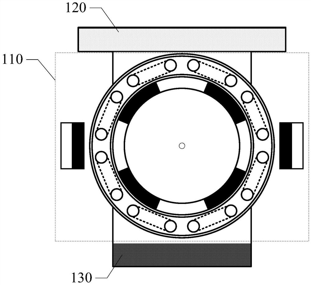
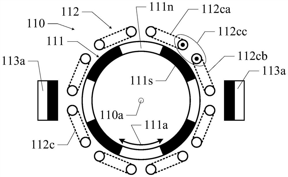
The invention discloses a scanning device for a laser radar, a control method of the scanning device and the laser radar. The scanning device comprises a resonance motor and a scanning mirror, wherein the resonant motor comprises a rotor and a stator; the rotor deflects from a balance position to a preset position around a rotating shaft; the stator comprises a return assembly which is suitable for enabling the rotor to return to the balance position around the rotating shaft; the scanning mirror is suitable for reflecting a light beam and carrying out optical scanning; and the scanning mirror is connected with the resonance motor so as to realize reciprocating swing of the scanning mirror. According to the scanning device, higher-frequency and larger-amplitude reciprocating swing of the scanning mirror can be realized with relatively lower driving power, low-power-consumption and large-angle reciprocating swing of the scanning mirror at a certain frequency can be realized, and the problem that the scanning view field range of a laser radar is limited due to the fact that the size of the scanning mirror is too small can be solved.

Description

technical field [0001] The invention relates to the field of laser radar, in particular to a scanning device for laser radar, a control method thereof, and laser radar. Background technique [0002] Lidar is a commonly used ranging sensor, which has the characteristics of long detection distance, high resolution, and low environmental interference. It is widely used in unmanned driving, intelligent robots, drones and other fields. In recent years, with the rapid development of autonomous driving technology, lidar, as the core sensor of distance perception, has become indispensable. [0003] In lidar, a beam of light is reflected by a reflective surface of a scanning device to form a beam for scanning. One type of scanning device used for laser radar is to use a vibrating mirror to realize scanning through the reciprocating motion of the reflecting surface of the vibrating mirror. In order to obtain a higher scanning frequency, the scanning device in the lidar often uses a ...

Claims


Application Information

Patent Timeline
IPC IPC(8): G01S17/08G01S7/481G01S7/48
CPCG01S17/08G01S7/4811G01S7/4802
Inventor 高永丰向少卿
Owner HESAI TECH CO LTD
Why Eureka
Eureka Blog
Learn More