Spring curtain lifting and collecting mechanism

A collection mechanism and curtain technology, applied in the direction of instruments, projection devices, optics, etc., can solve the problems of inconvenient removal and replacement, trouble, etc., and achieve the effect of improving the display effect, reducing the difficulty and reducing the overall structure noise.

Active Publication Date: 2022-01-04
JIANGSU SHUNHE INTERNET OF THINGS TECH CO LTD
View PDF10 Cites 1 Cited by
  • Summary
  • Abstract
  • Description
  • Claims
  • Application Information

AI Technical Summary

Problems solved by technology

"However, the parts used to remove the dust on the screen in this device are not easy to dismantle and replace at any time. Among them, the dust removal parts are used for a long time, and when they fail, it is more troublesome.

Method used


Image

  • Spring curtain lifting and collecting mechanism
  • Spring curtain lifting and collecting mechanism
  • Spring curtain lifting and collecting mechanism

Examples


Embodiment 1

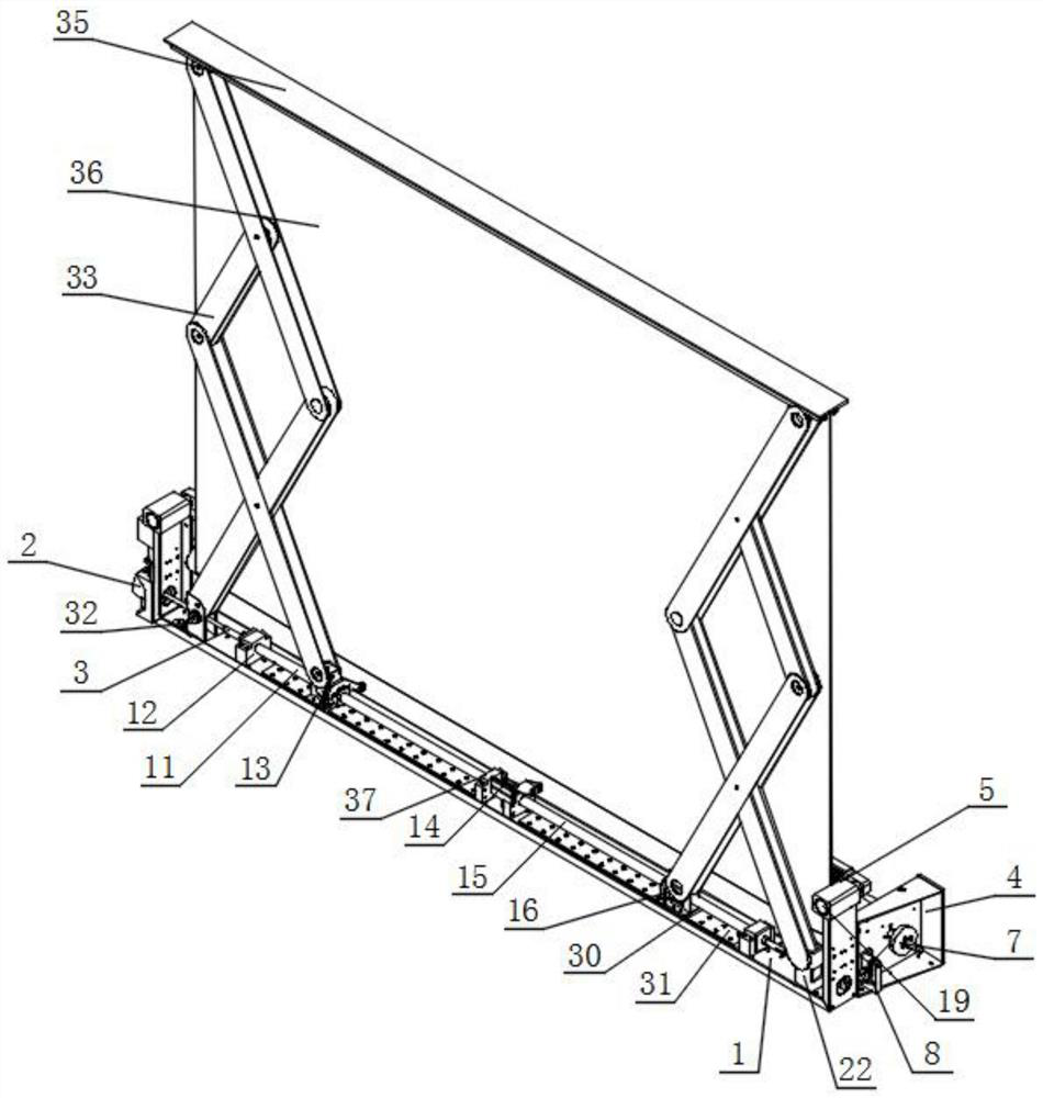
[0042] Such as figure 2 and Figure 4 Shown, a kind of spring realizes curtain lifting and collecting mechanism, comprises bottom frame 1, servo motor 2, shaft coupling 3, collection box 4 and fixed block 5, and the side outer wall of bottom frame 1 is equipped with servo motor 2, and servo motor The output end of 2 is equipped with a rotating shaft, and one end of the rotating shaft is installed with a coupling-3, and one end of the coupling-3 extends into the interior of the bottom frame 1;

[0043] Specifically, the bottom frame 1 provides a relatively stable installation space for the components above it, and facilitates the mutual cooperation between the components. After the servo motor 2 is started, the shaft installed at the output end can rotate clockwise or counterclockwise accordingly. It is used to drive the coupling-3 installed at one end of the rotating shaft to follow the rotation, the coupling-3 is used to connect the rotating shaft and the screw rod-11, and ...

Embodiment 2

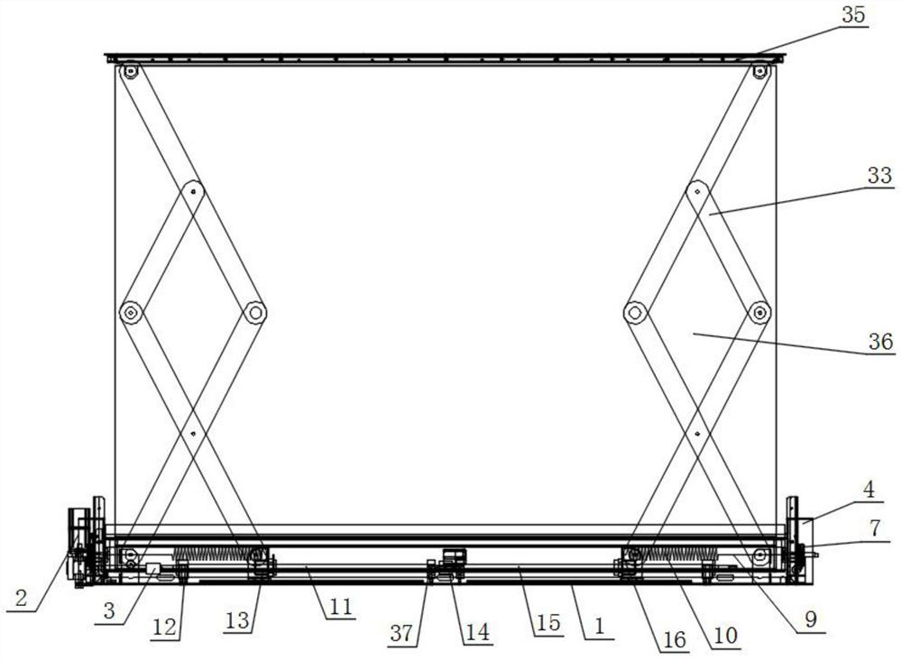
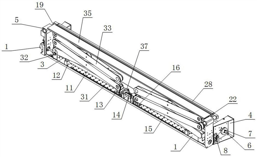
[0050] Such as figure 1 , image 3 As shown, the end of the coupling-3 away from the servo motor 2 is equipped with a screw-11, the outer surface of the screw-11 is equipped with a support seat-12, and the bottom of the support seat-12 is connected to the bottom wall of the bottom frame 1 Fitting, screw nut 13 is installed on the outer surface of screw rod 11, and the outer wall of the side of screw nut 13 close to servo motor 2 is connected with one end of one group of springs 10, and one end of screw rod 11 is installed There is a coupling two 14, and the end of the coupling two 14 away from the screw one 11 is equipped with a screw two 15, and the outer surface of the screw two 15 is equipped with a screw nut two 16, and the screw nut two 16 is far away from the servo motor 2 One side of the outer wall is connected with one end of another group of springs 10.

[0051] Specifically, screw rod one 11 is combined into a whole through coupling two 14 and screw rod two 15, and...

Embodiment 3

[0053] Such as Figure 5 , Figure 6 and Figure 8 As shown, the fronts of two groups of fixed blocks 5 are all provided with thread grooves 17, the inwalls of thread grooves 17 are provided with threaded sleeves 18, and the inwalls of threaded sleeves 18 are equipped with electric telescopic rods 19, and the back sides of electric telescopic rods 19 extend Out of the inside of the threaded groove 17, a connecting block 20 is installed on the backs of two groups of electric telescopic rods 19, and a groove 21 is arranged on the front of the connecting block 20, and the inner wall of the groove 21 is fitted with the outer wall of the electric telescopic rod 19, one of them One side outer wall of the group connection block 20 is equipped with a combination frame body 22, the top of the combination frame body 22 is provided with a notch 23, the front of the combination frame body 22 is provided with a through groove 24, and the inwall of the notch 23 is provided with a sponge st...


PUM


Abstract

The invention discloses a spring curtain lifting and collecting mechanism which comprises a bottom frame, a servo motor, a first coupler, a collecting box and a fixing block, the servo motor is installed on the outer wall of one side of the bottom frame, a rotating shaft is installed at the output end of the servo motor, and the first coupler is installed at one end of the rotating shaft; fixing blocks are mounted on the two sides of the top of the bottom frame; and two sets of collecting boxes arranged side by side are installed on the back face of the bottom frame, a curtain collecting roller is installed on the outer wall of one side of one set of collecting boxes in a penetrating mode, two sets of steel rope collectors arranged side by side are installed on the outer surface of the curtain collecting roller, and steel rope guide mechanisms are installed on the inner walls of one sides of the two sets of collecting boxes. According to the invention, a group of motors are adopted for control, the difficulty in control can be reduced, the opening force of the curtain sheets can be controlled to a certain extent through the springs, the curtain dust removal operation can be carried out in the opening process of the curtain, and a part for dust removal is clamped and connected with the combined frame body, so that the detachable performance is realized.

Description

technical field [0001] The invention relates to the technical field of elevating and collecting mechanisms, in particular to a spring-realized elevating and collecting mechanism for curtains. Background technique [0002] Curtain is an indispensable equipment on the stage of various types of theaters, theaters, auditoriums, clubs, studios, etc. It plays a role in decorating the stage and improving the performance effect. When it is used, it needs to use a lifting structure to assist the curtain to rise. and rewind. [0003] The defective that existing curtain lifting collection mechanism exists is: [0004] 1. The patent document CN112987474A discloses a floor-mounted electric liftable projection screen, "including a housing, a screen, a reel mechanism, and a lifting bracket; the reel mechanism is composed of a motor and a reel, and the lower end of the screen is connected to the reel and rolled Wound on the reel; the curtain lifting bracket is composed of a beam and four ...

Claims


Application Information

Patent Timeline
Patent Type & Authority Applications(China)
IPC IPC(8): G03B21/58
CPCG03B21/58
Inventor 施跃华
Owner JIANGSU SHUNHE INTERNET OF THINGS TECH CO LTD
Why Eureka
Try Eureka