
High-speed punching machine cutting mechanism and cutting method thereof

A technology of high-speed punching machine and power transmission mechanism, which is applied in the direction of punching machine, press machine, metal processing equipment, etc. It can solve the problems that the cutting head cannot be replaced, the transmission parts of the device are worn out, and the service life is not long, so as to achieve post-maintenance Low cost, stable force, energy-saving effect

Inactive Publication Date: 2022-01-07
广东红荔枝新材料科技有限公司
View PDF0 Cites 0 Cited by
  • Summary
  • Abstract
  • Description
  • Claims
  • Application Information

AI Technical Summary

Problems solved by technology

[0003] In the prior art, a special cutting head is generally provided at the bottom of the high-speed punching machine to facilitate the cutting of material parts, but the existing cutting mechanism is not stable enough, the wear between the transmission parts of the device is large, and the service life is not long. It is long, and the maintenance cost is high in the later period. In addition, it is often necessary to replace the cutting head during use, so as to use different cutting heads for different plates. In the prior art, there is generally only one set of cutting heads and It is fixed on the stamping platform with bolts. It is time-consuming and labor-intensive to replace. It is necessary to remove the old cutting head after stopping the machine, and then install and fix the new cutting head. This operation is time-consuming and laborious, and it is impossible to realize fast cutting. Replacement of cutting heads, when there are many shapes of plate cutting, it is a waste of time to repeatedly replace cutting heads. Aiming at the deficiencies of the prior art, the invention discloses a high-speed punch cutting mechanism to solve the above problems

Method used


Image

  • High-speed punching machine cutting mechanism and cutting method thereof
  • High-speed punching machine cutting mechanism and cutting method thereof
  • High-speed punching machine cutting mechanism and cutting method thereof

Examples


Embodiment 1

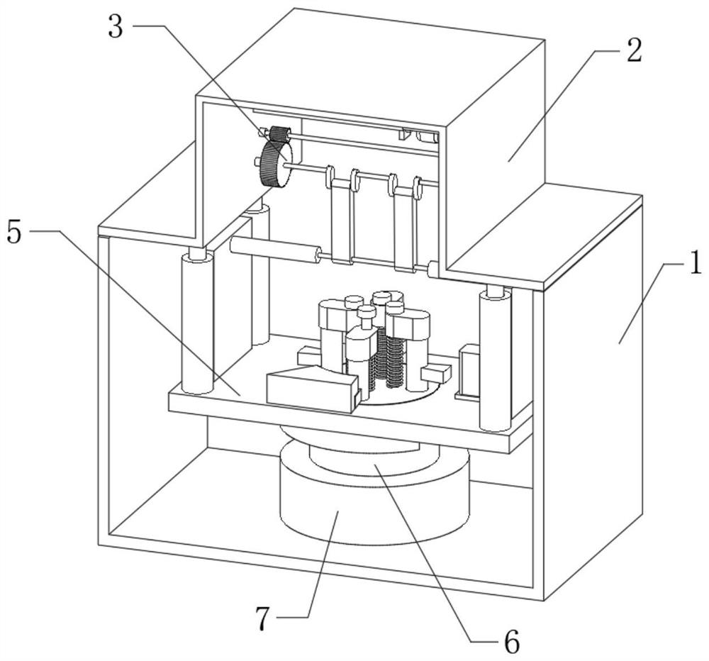
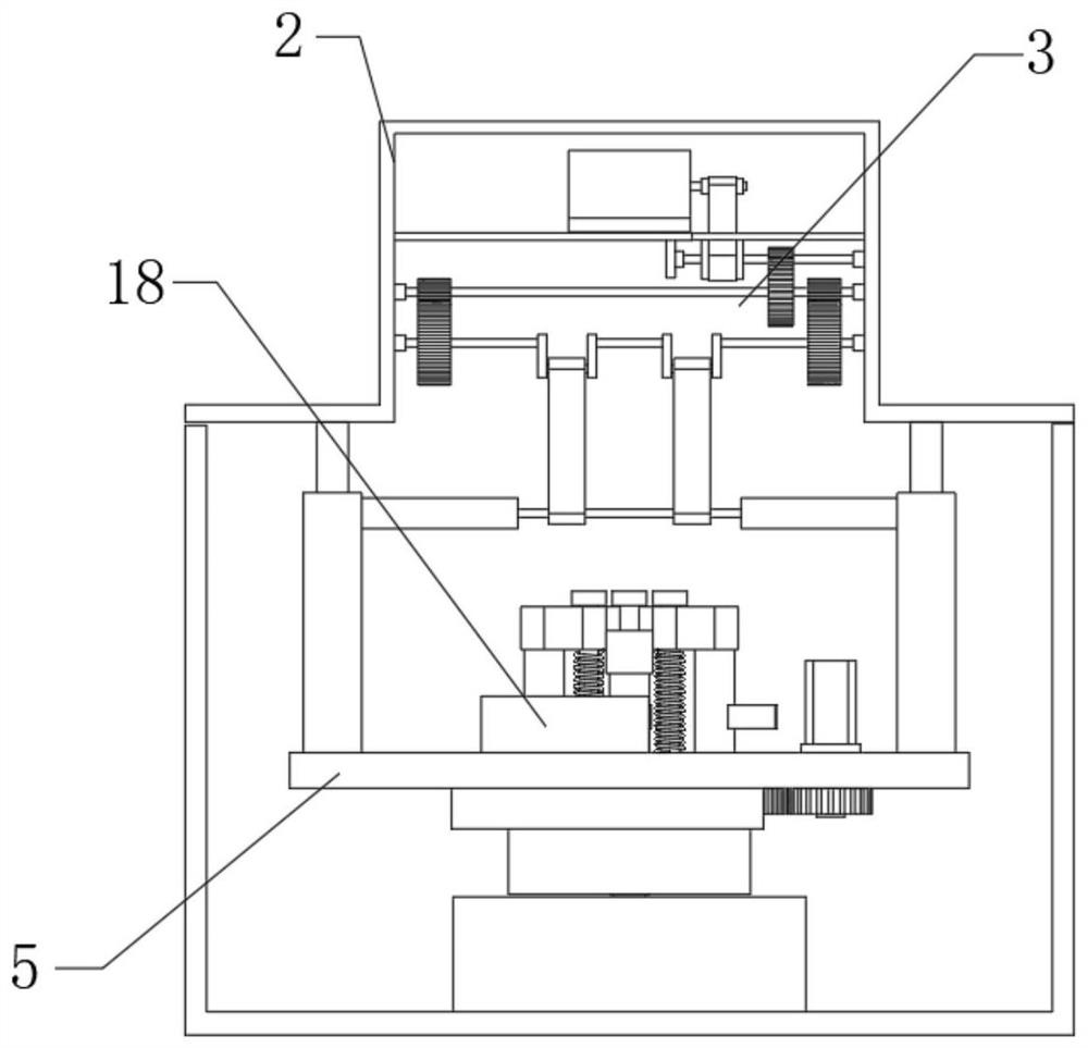
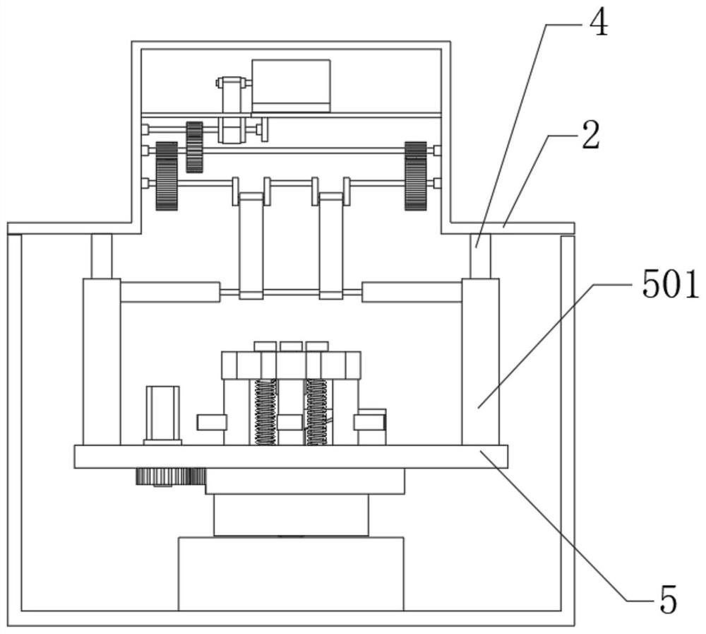
[0041] The embodiment of the present invention discloses a high-speed punch cutting mechanism, such as Figure 1-10 shown, including:

[0042] The bottom frame 1 of the high-speed punch press, the top frame 1 of the high-speed punch press bottom is fixedly connected with the top frame 2 of the high-speed punch press, the bottom of the top frame 2 of the high-speed punch press is provided with a power transmission mechanism 3, and the bottom of the power transmission mechanism 3 is connected with a lifting platform 5, the lifting platform 5 is rotatably connected with a cutting cylindrical base 6, the bottom of the cutting cylindrical base 6 is provided with a cutting head main body 14, and the bottom frame 1 of the high-speed punch press is provided with a lower support base 7;

[0043] The automatic replacement mechanism of the cutting head, the automatic replacement mechanism of the cutting head includes an outer toothed disc 8, the outer toothed disc 8 is fixedly connected ...

Embodiment 2

[0059] The embodiment of the present invention discloses a high-speed punch cutting mechanism, such as Figure 1-10 shown, including:

[0060] The bottom frame 1 of the high-speed punch press, the top frame 1 of the high-speed punch press bottom is fixedly connected with the top frame 2 of the high-speed punch press, the bottom of the top frame 2 of the high-speed punch press is provided with a power transmission mechanism 3, and the bottom of the power transmission mechanism 3 is connected with a lifting platform 5, the lifting platform 5 is rotatably connected with a cutting cylindrical base 6, the bottom of the cutting cylindrical base 6 is provided with a cutting head main body 14, and the bottom frame 1 of the high-speed punch press is provided with a lower support base 7;

[0061] The automatic replacement mechanism of the cutting head, the automatic replacement mechanism of the cutting head includes an outer toothed disc 8, the outer toothed disc 8 is fixedly connected ...


PUM


Abstract

The invention discloses a high-speed punching machine cutting mechanism, and relates to the field of machining equipment. The high-speed punching machine cutting mechanism comprises a high-speed punching machine bottom frame and an automatic cutting head replacing mechanism. When the high-speed punching machine cutting mechanism is used, the cutting effect on cutting materials is good; when a cutting head main body is replaced, manual disassembly and assembly of the cutting head main body are not needed, and the cutting head main body can be automatically stored and popped up to be replaced only by controlling starting and stopping of a servo motor body; the multiple groups of cutting head bodies are arranged on the cylindrical cutting base, so that repeated switching of the multiple groups of cutting head bodies is facilitated, the time for replacing the cutting head bodies is greatly saved, the cutting head bodies do not need to be specially and manually replaced, and the physical strength of workers is also saved; and a lifting platform is driven by a power transmission mechanism, and moves stably up and down in a reciprocating manner, so that the good cutting effect on materials is guaranteed.

Description

technical field [0001] The invention relates to the technical field of mechanical processing equipment, in particular to a high-speed punch cutting mechanism and a cutting method thereof. Background technique [0002] A punching machine is a stamping press. In national production, the stamping process saves materials and energy compared with traditional machining, has high efficiency, does not require high technical requirements for operators, and can be machined through various mold applications. These advantages of products that cannot be achieved, so its use is becoming more and more extensive. The stamping production of high-speed punching machine is mainly for sheet metal. Through the mold, it can make blanking, punching, forming, deep drawing, trimming, fine blanking, shaping, riveting and extrusion parts, etc., which are widely used in various fields. [0003] In the prior art, a special cutting head is generally provided at the bottom of the high-speed punching mach...

Claims


Application Information

Patent Timeline
Patent Type & Authority Applications(China)
IPC IPC(8): B21D37/04B21D37/00B30B1/26B30B15/00
CPCB21D37/04B21D37/00B30B15/00B30B1/26
Inventor 梁瑞庭赵永薛生利绍学章
Owner 广东红荔枝新材料科技有限公司
Learn More