Beam and slab cast-in-place concrete partition system

A concrete, cast-in-place technology, applied in the direction of formwork/formwork/work frame, on-site preparation of building components, connection of formwork/formwork/work frame, etc. Poor concrete effect, easy to be washed away by concrete and other problems, to achieve the effect of easy disassembly and assembly

Pending Publication Date: 2022-01-07
中铁一局集团建筑安装工程有限公司 +1
View PDF0 Cites 0 Cited by
  • Summary
  • Abstract
  • Description
  • Claims
  • Application Information

AI Technical Summary

Problems solved by technology

[0005] In view of the above-mentioned related technologies, the inventor believes that the airtightness and strength of the steel wire mesh are limited, and the overall softness of the steel wire mesh, the intersection of different steel meshes is easily washed away by the concrete, which makes the effect of actually partitioning the concrete not good.

Method used


Image

  • Beam and slab cast-in-place concrete partition system
  • Beam and slab cast-in-place concrete partition system
  • Beam and slab cast-in-place concrete partition system

Examples


Embodiment 1

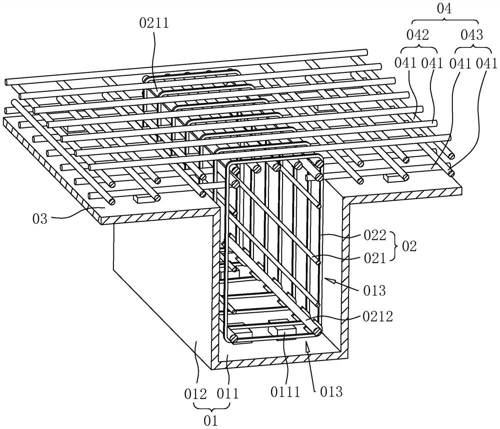
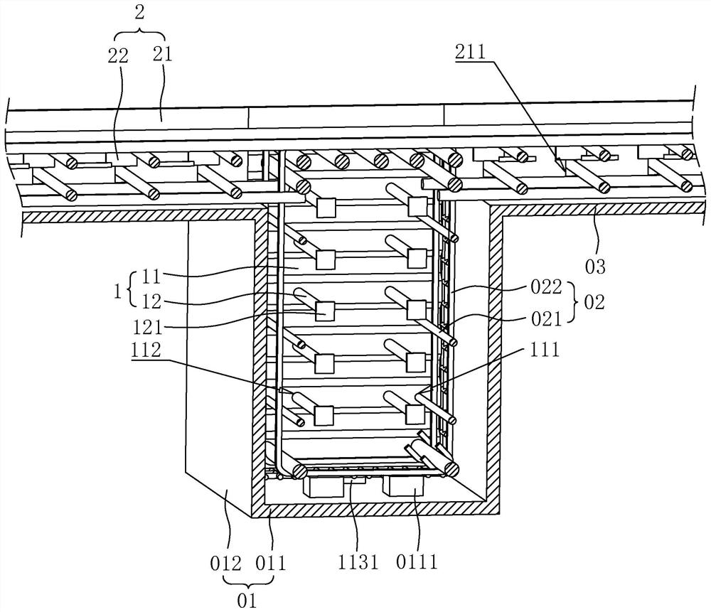
[0061] refer to figure 2 , a beam-slab cast-in-place concrete partition system includes a beam sealing member 1 and a plate sealing member 2 .

[0062] refer to figure 2 , The beam closure member 1 includes a partition plate 11 and a shear bar 12 .

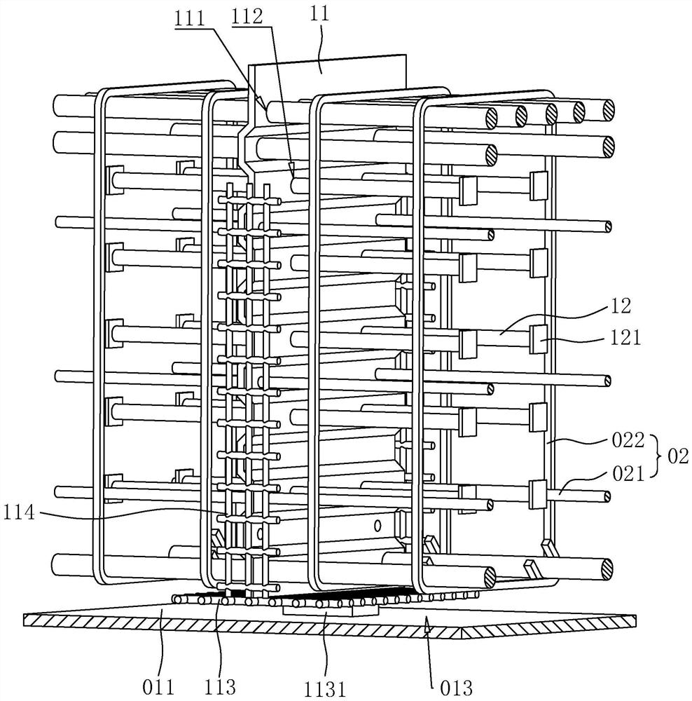
[0063] refer to figure 2 and image 3 , the partition 11 is arranged on the beam reinforcement skeleton 02. In this embodiment, the partition 11 is a concave-convex plate with a rectangular shape, and the length direction of the partition 11 is arranged along the vertical direction. In other embodiments, the partition 11 can be Inclined setting; in this embodiment, the partition 11 is a profiled steel plate, and in other embodiments, the partition 11 can be a hard seamless board such as a corrugated steel plate or a corrugated board; the partition 11 is located between two stirrups 022 , a plurality of first through holes 111 are opened on the partition 11, and the first through holes 111 are used for passing through the lo...

Embodiment 2

[0078] The difference between this embodiment and Embodiment 1 lies in that the anchoring structure 121 is different, the fixing method of the first steel wire mesh 113 is different, the structure of the beam blocking part 1 is different, and the structure and fixing method of the plate blocking part 2 are different.

[0079] refer to Figure 8 , in the present embodiment, the anchoring structure 121 is a nut, and each two ends of each shearing steel bar 12 tendons are threadedly connected with an anchoring structure 121; welding.

[0080] refer to Figure 8 , in this embodiment, the end of the partition 11 away from the bottom template 011 is located on the side of the top row of ribs 0211 close to the bottom template 011, and the end of the partition 11 away from the bottom template 011 is in contact with the top row of ribs 0211, and the partition 11 The end close to the bottom template 011 is located on the side of the bottom row of ribs 0212 away from the bottom templat...

Embodiment 3

[0095] The difference between this embodiment and Embodiment 2 is that the structure of the partition 11 is different, the structure of the blocking plate 5 is different, the connection mode of the blocking plate 5 and the partition 11 is different, the fixing method of the first steel wire mesh 113 is different, and the movable The structure of piece 22 is different.

[0096] refer to Figure 12 , in this embodiment, the partition 11 is a concave-convex plate with several bumps 115 and several grooves 116 on the surface of the partition, the basic plate shape of the partition 11 is a rectangular steel plate, and the two board surfaces of the partition 11 A plurality of rectangular block-shaped bumps 115 are uniformly connected, and a groove 116 with a rectangular port is opened at the position where the partition 11 is provided with the bump 115. The bump 115 and the groove 116 at the same position on the partition 11 are located On the board walls on different sides, a groo...


PUM


Abstract

The invention relates to a beam and slab cast-in-place concrete partition system, and relates to the field of building cast-in-place. The beam and slab cast-in-place concrete partition system comprises a beam plugging piece, and the beam plugging piece comprises partition plates and a plate plugging piece. A partition plate is a concave-convex plate, the partition plate is used for a beam steel reinforcement framework to penetrate through, and the partition plate is fixedly connected with the beam steel reinforcement framework; and the plate plugging piece comprises at least one plugging plate, the plugging plates are arranged on plate formworks and used for intercepting concrete on the plate formworks, and the partition plates abut against the plugging plates. The beam and slab cast-in-place concrete partition system has the effect that the concrete in the beam-slab system can be more effectively partitioned.

Description

technical field [0001] The present application relates to the field of cast-in-place buildings, in particular to a beam-slab cast-in-place concrete partition system. Background technique [0002] In the process of pouring concrete in the beam-slab cast-in-place system, sometimes due to design or construction requirements, it is necessary to pour in sections, and sometimes different grades of concrete need to be poured separately during pouring. Before pouring concrete in the system, it is necessary to set up a structure to intercept the concrete to intercept and partition the concrete in the formwork. [0003] refer to figure 1 , in the related art, the beam-slab cast-in-place frame includes a beam formwork 01 and a slab formwork 03; the beam formwork 01 includes a bottom formwork 011 and a side formwork 012, and the bottom formwork 011 and the side formwork 012 form a pouring space, and a beam is built in the pouring space Reinforcement skeleton 02; both sides of beam for...

Claims


Application Information

Patent Timeline
Patent Type & Authority Applications(China)
IPC IPC(8): E04G13/00E04G13/04E04G11/36E04G17/00E04C5/04E04C5/06
CPCE04G13/00E04G13/04E04G11/36E04G17/00E04C5/04E04C5/06
Inventor 张海亮张奉超别红亮刘堃姚睿王丹涛杨东雷刘金果冯小朋
Owner 中铁一局集团建筑安装工程有限公司
Why Eureka
Try Eureka