
A method for maintenance and cooling of hot air pipe system

A technology of hot air pipes and hot air main pipes, which is applied to pipeline heating/cooling, pipes/pipe joints/fittings, mechanical equipment, etc., which can solve problems such as unreachable, time-consuming, and potential safety hazards, and improve safety assurance capabilities, Improved cooling efficiency and large pumping force

Active Publication Date: 2022-04-12
SGIS SONGSHAN CO LTD
View PDF11 Cites 1 Cited by
  • Summary
  • Abstract
  • Description
  • Claims
  • Application Information

AI Technical Summary

Problems solved by technology

Before maintenance, the traditional cooling method of the existing hot air pipe system is usually to open the maintenance manhole, and then install an axial flow fan to force the air to cool outside, and cooperate with pumping water to cool down; the axial flow fan to force the air to cool outside usually takes 10 Days to 15 days, the hot air temperature is high in the early stage, and under the condition of many maintenance personnel, safety control is difficult and time-consuming; in addition, fetching water to cool down will cause great damage to other refractory materials that do not need to be replaced, and it is easy to cause other problems. Security risks
Therefore, the traditional cooling method does not meet the fast-paced production of modern large blast furnaces, and cannot meet the high safety and quality control requirements. Therefore, there is an urgent need for a rapid cooling optimization method at the hot blast piping maintenance site, which can be used with blast furnaces , The main body of the hot blast stove is completely cut off, which does not affect the independent construction of the hot blast piping system

Method used


Image

  • A method for maintenance and cooling of hot air pipe system

Examples


Embodiment Construction

[0025] The present invention will be described in further detail below in conjunction with the accompanying drawings and embodiments. It should be understood that the specific embodiments described here are only used to explain the present invention, but not to limit the present invention. In addition, it should be noted that, for the convenience of description, only some structures related to the present invention are shown in the drawings but not all structures.

[0026] In the description of the present invention, unless otherwise clearly specified and limited, the terms "connected", "connected" and "fixed" should be understood in a broad sense, for example, it can be a fixed connection, a detachable connection, or an integrated ; It can be a mechanical connection or an electrical connection; it can be a direct connection or an indirect connection through an intermediary, and it can be the internal communication of two components or the interaction relationship between two ...


PUM


Abstract

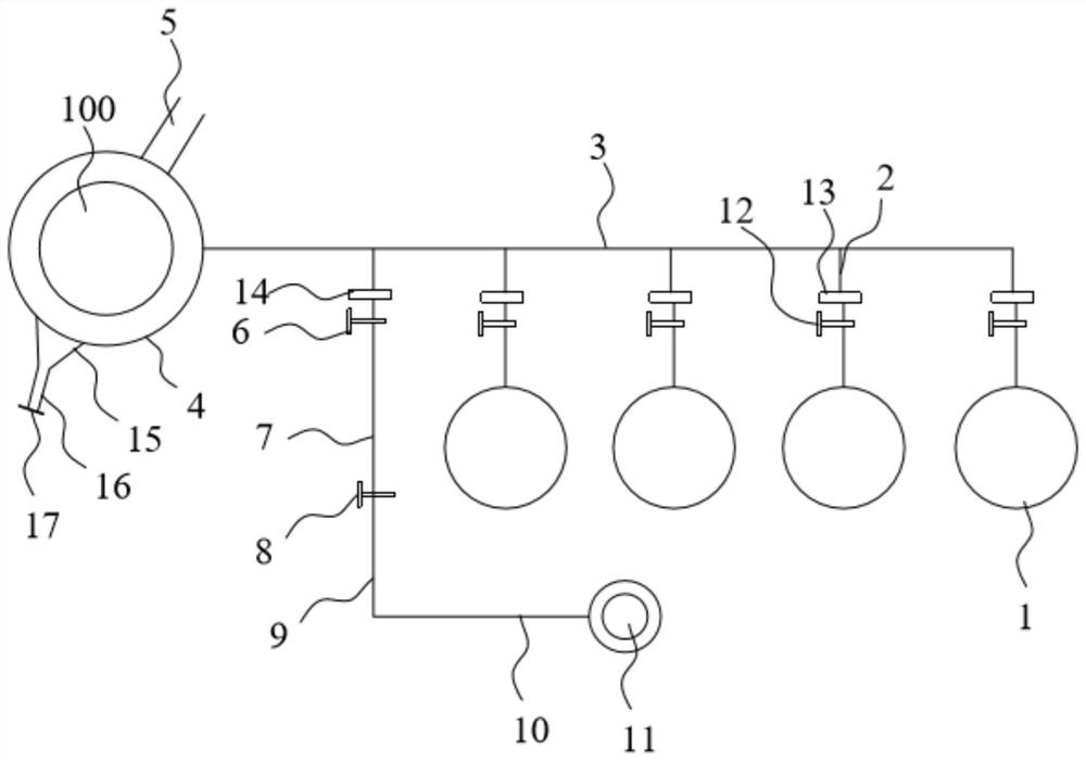
The invention belongs to the technical field of blast furnace smelting, and in particular relates to a method for maintaining and cooling a hot air duct system, comprising the following steps: step S1, after the blast furnace is completely stopped for wind, remove the tuyere blowing pipe and the elbow, and install the middle section blind plate; step S2, Turn on the combustion-supporting fan to cool down the reverse supply air. The cooling route is followed by the combustion-supporting fan, the combustion-supporting air pipe, the reverse supply air pipe, the mixing air pipe, the hot air main pipe, the hot air surrounding pipe and the reverse flow pipe, until the temperature drops to the first set value; step S3, close the air mixing valve, turn on the first axial flow fan to cool down until the cooling rate is less than the second set value; Step S4, turn on the second axial flow fan to cool down until the temperature drops to the third set value; Step S5, Install hot blast valve blinds, mixing valve blinds, and middle section blinds; check whether the piping system meets the operating conditions. The maintenance and cooling method of the hot air duct system of the present invention greatly improves the cooling efficiency, does not need to draw water in the cooling process, does not cause damage to refractory materials, and improves the safety guarantee capability of construction operations.

Description

technical field [0001] The invention relates to the technical field of blast furnace smelting, in particular to a maintenance and cooling method for a hot air piping system. Background technique [0002] The hot blast pipe system is the collective name of the hot blast branch pipe, hot blast main pipe and hot blast surrounding pipe, and is the only pipeline for the hot blast stove to deliver high temperature hot blast into the blast furnace. When the hot blast piping system needs to be repaired, in the two special cases where the hot blast furnace needs reverse air supply for heat preservation and the reverse flow pipe is directly above the hot blast surrounding pipe, the cooling period of the hot blast piping system is the bottleneck and restrictive condition of the entire maintenance period. . Before maintenance, the traditional cooling method of the existing hot air pipe system is usually to open the maintenance manhole, and then install an axial flow fan to force the ai...

Claims


Application Information

Patent Timeline
Patent Type & Authority Patents(China)
IPC IPC(8): F16L53/70
CPCF16L53/70
Inventor 杨国新王忠连江滔艾中路温元泉张小军庄锦填郑帮候赞兵卓阿诚
Owner SGIS SONGSHAN CO LTD
Learn More