Multi-port valve

A multi-channel and valve technology, applied in multi-way valves, valve details, valve devices, etc., can solve the problems of energy saving and consumption reduction, affecting production efficiency, increasing production costs, etc., to achieve cost saving, convenient use and maintenance. , the effect of simple structure

Pending Publication Date: 2022-01-07
DALIAN CONSERVATION SCI & TECH CO LTD
View PDF0 Cites 0 Cited by
  • Summary
  • Abstract
  • Description
  • Claims
  • Application Information

AI Technical Summary

Problems solved by technology

It is understood that the current valves for such high-temperature conditions are not useful: some users directly block the valves and only use one pipeline to transport high-temperature materials. When there is a problem with the pipeline or equipment, they can only stop for maintenance, which undoubtedly greatly increases Reduced production costs, affecting production efficiency, energy saving and consumption reduction is out of the question

Method used


Image

  • Multi-port valve
  • Multi-port valve
  • Multi-port valve

Examples


Embodiment 1

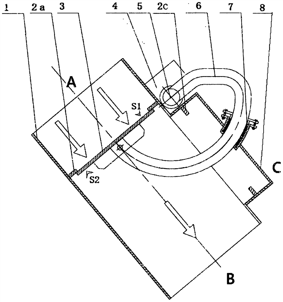
[0035] A three-way valve, such as figure 1As shown, it includes a valve body 1, a valve plate 3, a driving structure 4, a main shaft 5 and a crank 6; the valve body 1 has three medium flow ports A, B, and C, and the A port and the B port are coaxial and the A port is opposite to each other. Port B is located upstream of the flow direction of the medium, port C is not coaxial with ports A and B, and is open sideways to the axis of ports A and B; the inner walls of port A and port C are respectively provided with valve seats 2a and 2c, and the valve seats are located The medium flows to the downstream, while the C port and its valve seat 2c are located above the axis of the A and B ports; the valve plate 3 is set in the valve body 1, and has two sealing surfaces S1 and S2 to serve as the corresponding valve The sealing surface S1 and S2 are respectively located on the two axial end surfaces of the valve plate 3; the main shaft 5 is located outside the valve body 1, and the crank...

Embodiment 2

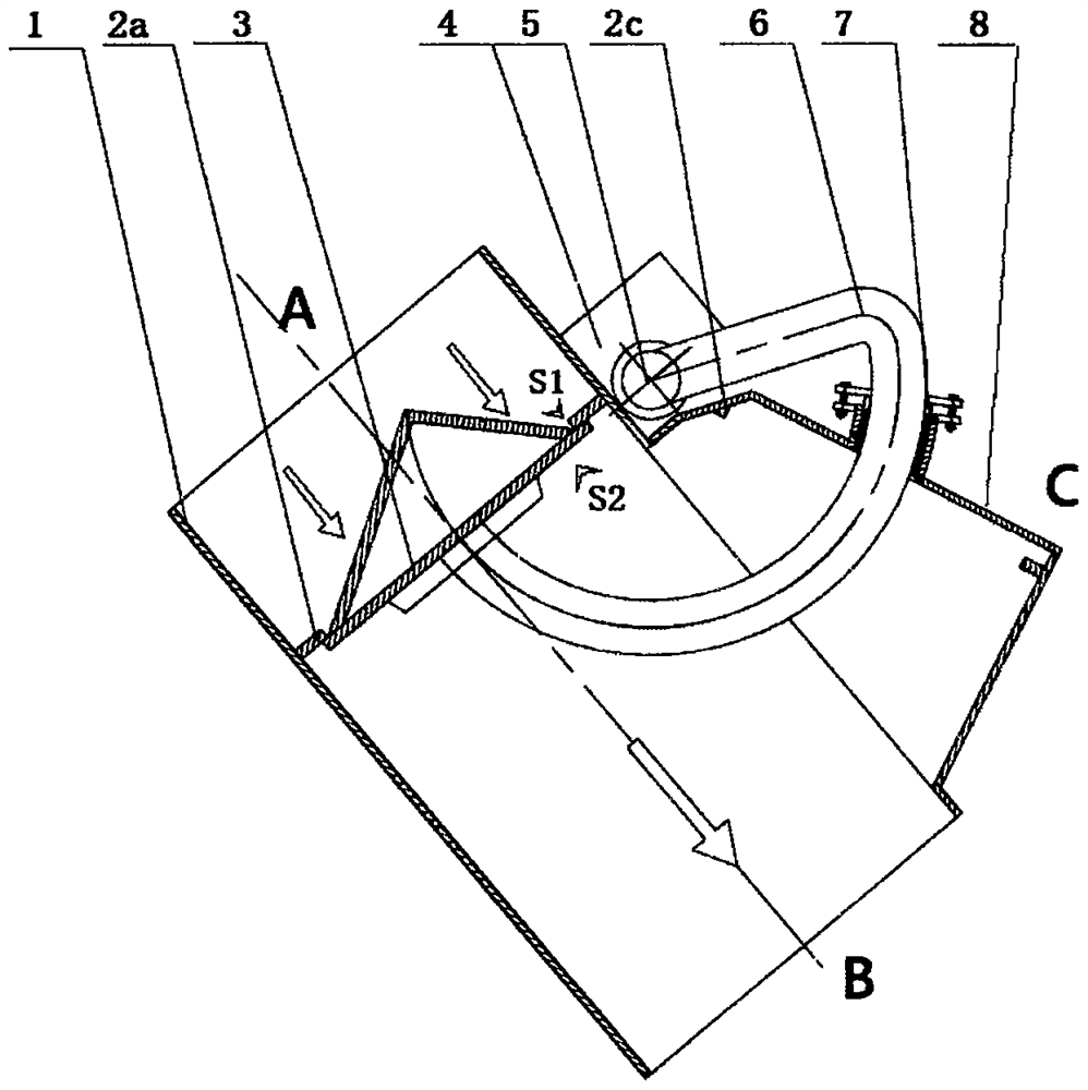
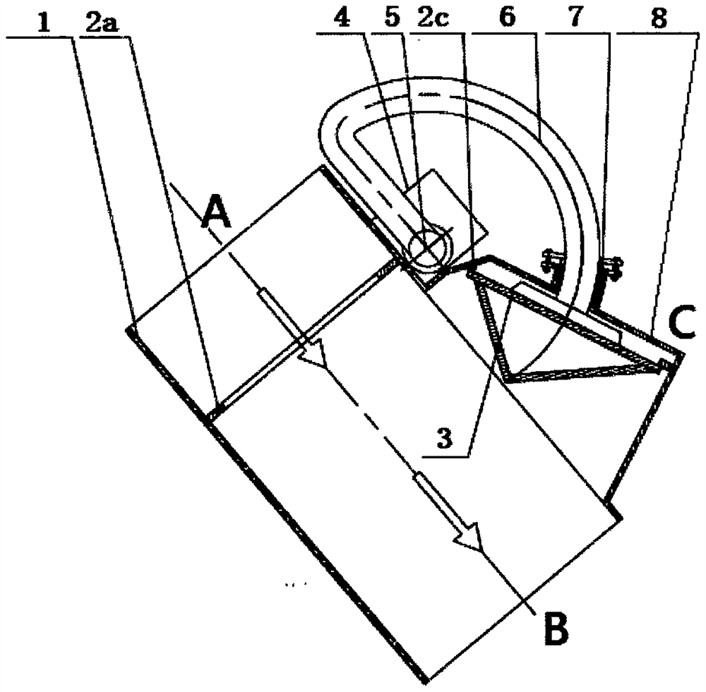
[0037] A three-way valve, such as figure 2 and image 3 Shown; Same as Embodiment 1, it has 3 media flow ports A, B, C, including valve body 1, valve plate 3, drive structure 4, main shaft 5, crank 6 and crank packing box 7, etc.; The main shaft is set outside the valve body 1, and the crank 6 adopts a fan-like ring structure and passes through the crank packing box 7 on the inspection hole cover 8 of the port C to penetrate inside and outside the valve body 1 and drive The valve plate 3 rotates, that is, the valve plate 3 rotates around the main shaft 5 to realize the position change between the valve seat 2a of the A port and the valve seat 2c of the C port, and through its two axial end faces Two opposite sealing surfaces S1, S2 are respectively connected with the valve seat 2a of port A (such as figure 2 shown) and the valve seat 2c of port C (such as image 3 shown) fit and seal to realize its two-position three-way function;

[0038] The difference from Embodiment ...

Embodiment 3

[0040] A three-way valve, such as Figure 4 and Figure 5 As shown, its overall structure is basically the same as that of Embodiment 1, including a valve body 1, a valve plate 3, a main shaft 5, a fan-like annular crank 6, and a crank packing box 7; the main shaft 5 is arranged outside the valve body 1 , the valve plate 3 has two sealing surfaces S1, S2 which are respectively located on the two axial end surfaces of the valve plate 3, and the valve body has three media flow ports A, B, C. The function realization of its two-position three-way is also identical with embodiment 1.

[0041] The difference is that in the valve described in this embodiment, the inner wall of the valve body 1 and the axial end surface where the sealing surface S1 of the valve plate 3 is located are all covered with a thermal insulation lining 10 and a wear-resistant lining 9 in sequence, that is, on the The inner wall of the valve and the axial end surface of the valve plate are covered with a th...


PUM


Abstract

The invention relates to a multi-port valve. The multi-port valve comprises a valve body, a valve plate, a valve seat, a driving mechanism and a transmission mechanism. The valve plate is positioned in the valve body and is provided with more than two sealing surfaces S; the transmission mechanism comprises a main shaft and a crank; the main shaft is connected with the driving mechanism, and the crank is connected with the main shaft and the valve plate and drives the valve plate to move or be opened and closed between different ports of the valve. And the valve plate is attached to and sealed with the valve seats at the port positions through different sealing surfaces S at the different port positions of the valve. The multi-port valve has the outstanding effects of simple structure, convenience in use and maintenance, cost saving, safety and reliability, and energy conservation and consumption reduction; and the problems that the space of a control is limited and the strength of main metal parts, including a main shaft, of a valve body is sharply reduced under a high-temperature working condition are solved; and the multi-port valve can be widely applied to various different working conditions and pipelines for conveying different media.

Description

technical field [0001] The invention relates to a valve, in particular to a multi-channel valve. Background technique [0002] In the system equipment including petrochemical, coal, food, grain, papermaking, brewing and other fields, it involves the transportation of materials through pipelines, and the materials exist in gaseous, solid, liquid or two or more phases. Install different valves on the pipeline to adjust the flow, change the flow direction of the medium or cut off the effect; the selection of the valve will undoubtedly directly affect the production safety, reliability, efficiency, energy saving, etc.; choose the appropriate valve according to different working conditions. important. [0003] When the medium transported by the pipeline is a single material, if the flow adjustment or isolation is realized, a regulating valve or a blocking valve can be installed on the straight section of the pipeline. When the pipe diameter is large, the volume of the reversing...

Claims


Application Information

Patent Timeline
Patent Type & Authority Applications(China)
IPC IPC(8): F16K11/044F16K27/02F16K31/52F16L59/02F16L59/10F16L59/04
CPCF16K11/044F16K27/0263F16K31/521F16L59/028F16L59/10F16L59/04
Inventor 杨意相宗宗张扬帆李自强
Owner DALIAN CONSERVATION SCI & TECH CO LTD
Why Eureka
Try Eureka