Suspension machine body coal mining machine

A technology of shearer and fuselage, which is applied in the field of suspended shearer, which can solve the problems of complex transmission, limited space for downhole transportation, and large front and rear width of the fixed part.

Pending Publication Date: 2021-05-18
SHANGHAI TIANDI MINING EQUIP TECH CO LTD +2
View PDF0 Cites 0 Cited by
  • Summary
  • Abstract
  • Description
  • Claims
  • Application Information

AI Technical Summary

Problems solved by technology

However, in some designs, due to the consideration of the structure of the loading channel on the side of the drum, a part of the transmission of the fixed part is set above the conveyor trough, which not only affects the coal passing space, but also the front and rear width of the fixed part is too large, and the transportation space of the downhole is limited; The rocker arm adopts the structure of a planetary mechanism in the drum with a conventional structure, so the diameter of the drum cannot be small, making the shearer unsuitable for mining with a lower mining limit
There are also designs where the power and main deceleration parts are set on the side of the coal wall in front of the conveyor trough (that is, between the left and right rollers). Although the mining height can be lower, the transmission is relatively complicated, and the center of gravity of the fixed part and the swing part is relatively biased towards the coal wall. , has a certain adverse effect on the operation of the whole machine, especially under the condition of the down mining face

Method used


Image

  • Suspension machine body coal mining machine
  • Suspension machine body coal mining machine
  • Suspension machine body coal mining machine

Examples


Embodiment Construction

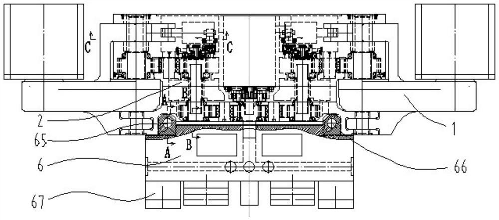
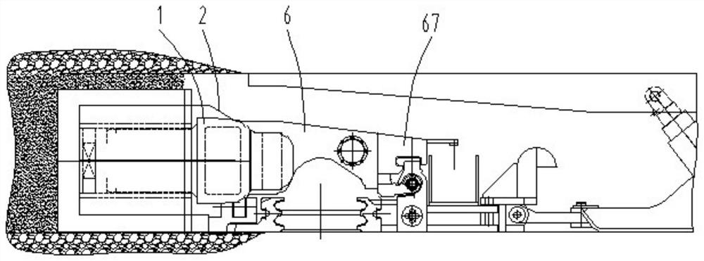
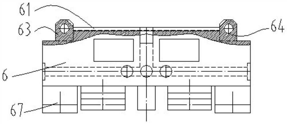
[0047] The invention discloses a coal mining machine with a suspended body, such as Figure 1-10 As shown, it includes a fixed reduction box 2, a bridge structure 6 and a jib 1. The fixed reduction box includes a fixed reduction box housing 21 and an oil cylinder 4 arranged in the fixed reduction box housing, a cutting motor 7 and a front-stage cutting transmission mechanism, and the output shaft of the cutting motor is connected to the front-stage cutting transmission. mechanism. The front-stage cutting transmission mechanism adopts a multi-stage large reduction ratio transmission mechanism combining a planetary mechanism 81 and a fixed shaft gear transmission mechanism. The output end of the preceding stage cutting transmission mechanism is the preceding final gear 82, and the preceding final gear is rotatably supported and installed in the housing of the fixed reduction box. The fixed reduction box housing and the bridge structure are arranged front and back and are detac...


PUM


Abstract

The invention relates to a suspension machine body coal mining machine. The suspension machine body coal mining machine comprises a fixed reduction gearbox, a gap bridge structure and an arm frame; the fixed reduction gearbox comprises a fixed reduction gearbox shell, an oil cylinder, a cutting motor and a front-stage cutting transmission mechanism, wherein the oil cylinder, the cutting motor and the front-stage cutting transmission mechanism are located in an inner cavity of the fixed reduction gearbox shell; the fixed reduction gearbox shell and the gap bridge structure are arranged front and back and detachably and fixedly connected; the arm frame comprises an arm frame shell and a rear-stage cutting transmission mechanism; a core part of a front-stage tail gear of the front-stage cutting transmission mechanism and a rear-stage head gear of the rear-stage cutting transmission mechanism form spline connection through a spline shaft; the arm frame shell is hinged to the fixed reduction gearbox shell, and the hinge axis coincides with the center line of spline connection; te two ends of the oil cylinder are hinged to the fixed reduction gearbox shell and the arm frame shell correspondingly; and the oil cylinder is located in front of the front-stage cutting transmission mechanism. The suspension machine body coal mining machine can achieve the purposes of channel loading and underground transportation at the same time, the transmission mechanisms are simple, and the gravity center of the whole coal mining machine can be improved through the overall layout.

Description

technical field [0001] The invention relates to a coal shearer with a suspended body, which is suitable for mining in a wide range of mining heights in thin or extremely thin coal seams. Background technique [0002] In the mining of thin coal seam lower limit or extremely thin coal seam conditions, in order to improve the adaptability of the cutting swing rocker to the coal seam, the cutting transmission system is usually set to consist of two parts: the fixed part of the short structure with power and the swing part of the output power . However, in some designs, due to the consideration of the structure of the loading channel on the side of the drum, a part of the transmission of the fixed part is set above the conveyor trough, which not only affects the coal passing space, but also the front and rear width of the fixed part is too large, and the space for downhole transportation is limited; The rocker arm adopts the structure of a planetary mechanism in the drum with a ...

Claims


Application Information

Patent Timeline
Patent Type & Authority Applications(China)
IPC IPC(8): E21C35/00E21C31/02F16H57/08F16H57/023F15B15/14
CPCE21C31/02E21C35/00F15B15/14F16H57/023F16H57/08F16H2057/02034F16H2057/02086
Inventor 章立强贠瑞光陶嵘王振乾董超朱红徐文锋黄秋来曹杨胡滔胡璟宋振顾恩洋丁海春王灿唐葆霖马子尧郭岱钱立全路潞王兆胜曾苛
Owner SHANGHAI TIANDI MINING EQUIP TECH CO LTD
Why Eureka
Try Eureka