Supercharge Your Innovation With Domain-Expert AI Agents!

Collet chuck type clamping device

A technology of clamping device and collet, which is applied in the direction of positioning device, clamping, support, etc., can solve the problems of cumbersome operation, low precision, high price, etc., achieve convenient installation and disassembly, improve installation efficiency, and reduce stress damage Effect

Pending Publication Date: 2022-01-11
江苏星晨高速电机有限公司
View PDF10 Cites 0 Cited by
  • Summary
  • Abstract
  • Description
  • Claims
  • Application Information

AI Technical Summary

Problems solved by technology

[0002] Collets are widely used in the existing spindle industry, but the existing collet-type spindles have low precision and complex structure, and the replacement of the collet positioning tool holder is complicated, and it is difficult to achieve the original accuracy after replacement. The high-precision positioning that can be provided abroad The handle is expensive and can cost tens of thousands
At present, many enterprises use the coil spring set on the shaft core to push the collet to load and unload the knife, but it is difficult to ensure the concentricity when the coil spring is directly set on the shaft core, and the coil spring itself does not have the function of precise positioning. Moreover, with repeated use, the coil spring wears out, making it more difficult to ensure concentricity, and disassembly and reinstallation requires re-calibration of concentricity, and the operation is more cumbersome. Therefore, a new technical solution is urgently needed to solve the above problems

Method used


Image

  • Collet chuck type clamping device
  • Collet chuck type clamping device
  • Collet chuck type clamping device

Examples


Embodiment 1

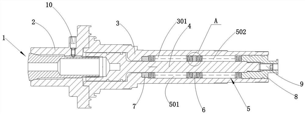
[0032]A collet-type clamping device, including a handle 2, a collet 1, and a broach device, the broach device includes a shaft core 3, at least one positioning spacer 6, a first disc spring assembly 501, The second disc spring assembly 502, a positioning washer 7, pull rod 4, pressure sleeve 8 and top wire 9, the head end of the collet 1 is inserted in the tail end of the knife handle 2 with interference, and the knife handle 2 is There are positioning pins in the radial direction, the tail end of the shaft core 3 is inserted in the head end of the handle 2 with interference, the shaft core 3 is provided with an axially penetrating cavity 301, and the pull rod 4 is movable through Set in the cavity 301, the tail end of the pull rod 4 is threadedly connected with the head end of the collet 1, and the head end of the pull rod 4 is threadedly connected with the tail end of the pressure sleeve 8, and the pressure sleeve 8 is arranged on the shaft core In the cavity 301 of 3, the f...

Embodiment 2

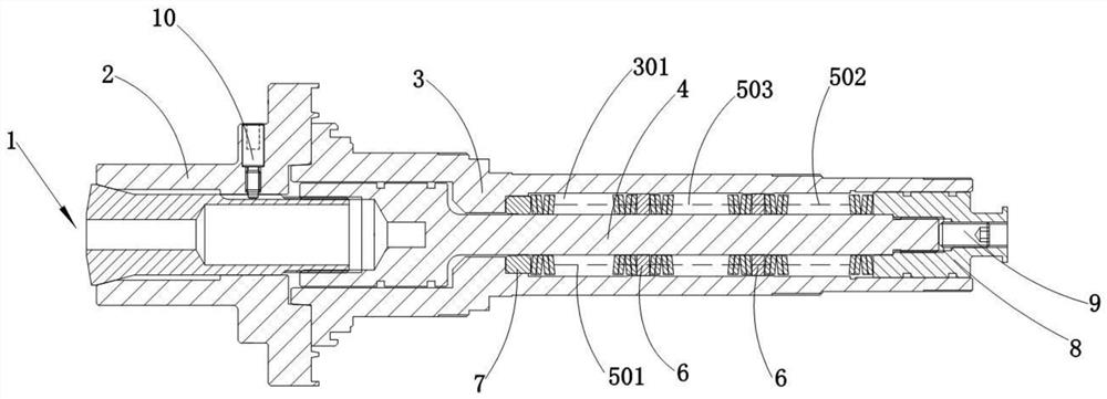
[0037] A collet-type clamping device, including a handle 2, a collet 1, and a broach device, the broach device includes a shaft core 3, two positioning spacers 6, a first disc spring assembly 501, a second Two disc spring assemblies 502, a third disc spring assembly 503, a positioning washer 7, a pull rod 4, a pressure sleeve 8 and a top screw 9, the head end of the collet 1 is inserted in the tail end of the handle 2 with interference, The knife handle 2 is provided with positioning pins in the radial direction, the tail end of the shaft core 3 is inserted in the head end of the knife handle 2 with interference, and the shaft core 3 is provided with a cavity 301 axially penetrating, The pull rod 4 is movably installed in the cavity 301, the tail end of the pull rod 4 is threadedly connected to the head end of the collet 1, the head end of the pull rod 4 is threaded to the tail end of the pressure sleeve 8, and the pressure sleeve 8 is threadedly connected. The sleeve 8 is set...


PUM


Abstract

The invention provides a collet chuck type clamping device which comprises a cutter handle, a collet chuck and a broach device. The broach device comprises a shaft core, at least one positioning space ring, disc spring assemblies, a positioning gasket, a pull rod, a pressing sleeve and a jackscrew; the head end of the collet chuck is inserted into the tail end of the cutter handle in an interference mode, the cutter handle is provided with a positioning piece in the radial direction, and the tail end of the shaft core is inserted into the head end of the cutter handle in an interference mode; a cavity penetrating in the axial direction is formed in the shaft core, the pull rod is movably arranged in the cavity in a penetrating mode, the pressing sleeve is arranged in the cavity of the shaft core, the disc spring assemblies are arranged on the pull rod in a sleeving mode, every two adjacent disc spring assemblies are separated through the corresponding positioning space ring, the peripheral faces of the positioning space rings are attached to the cavity wall of the cavity, and the positioning gasket is clamped in the cavity; and one end of the positioning gasket abuts against one disc spring assembly, the tail end of the pressing sleeve abuts against the other disc spring assembly, and the jackscrew is arranged in the pressing sleeve in a rotating mode and abuts against the head end of the pull rod. The collet chuck type clamping device is simple and easy to operate, long in service life, good in clamping effect and high in machining precision.

Description

technical field [0001] The invention relates to a clamping device, in particular to a collet type clamping device. Background technique [0002] Collets are widely used in the existing spindle industry, but the existing collet-type spindles have low precision and complex structure, and the replacement of the collet positioning tool holder is complicated, and it is difficult to achieve the original accuracy after replacement. The high-precision positioning that can be provided abroad Knife handles are expensive and cost tens of thousands. At present, many enterprises use the coil spring set on the shaft core to push the collet to load and unload the knife, but it is difficult to ensure the concentricity when the coil spring is directly set on the shaft core, and the coil spring itself does not have the function of precise positioning. Moreover, with repeated use, the coil spring wears out, making it more difficult to ensure concentricity, and disassembly and reinstallation r...

Claims


Application Information

Patent Timeline
IPC IPC(8): B23Q3/12
CPCB23Q3/12
Inventor 刘钊周磊
Owner 江苏星晨高速电机有限公司
Features
  • R&D
  • Intellectual Property
  • Life Sciences
  • Materials
  • Tech Scout
  • Unparalleled Data Quality
  • Higher Quality Content
  • 60% Fewer Hallucinations
Learn More