Supercharge Your Innovation With Domain-Expert AI Agents!

Structure for generating sliding arc and plasma igniter with structure

A plasma and sliding arc technology, applied in the direction of machines/engines, jet propulsion devices, gas turbine devices, etc., can solve the problems of insufficient arc energy and unadjustable, so as to improve the success rate of ignition, avoid energy waste, and ensure The effect of full exposure

Pending Publication Date: 2022-01-11
SHENYANG AEROSPACE UNIVERSITY
View PDF4 Cites 1 Cited by
  • Summary
  • Abstract
  • Description
  • Claims
  • Application Information

AI Technical Summary

Problems solved by technology

[0005] The prior art discloses the application of sliding arc in plasma igniter, such as ① Chinese invention patent application number: 201911272687.3, name: multi-anode sliding arc plasma igniter and ignition method based on secondary flow in combustion chamber; ② China Invention patent application number: 201911272688.8, name: a multi-cathode sliding arc plasma igniter; ③ Chinese invention patent application number: CN201711225205.X, name: aero-engine plasma jet igniter based on self-entrained air; ④ Chinese utility model Patent application number: CN109057972A, name: a pre-combustion type aircraft engine plasma igniter; the above schemes all use plasma to assist ignition to achieve reliable ignition under harsh conditions, and the advantage is that it can improve the lean combustion of fuel during ignition Limit, the disadvantage is that the arc energy generated during ignition is not very sufficient and cannot be adjusted

Method used


Image

  • Structure for generating sliding arc and plasma igniter with structure
  • Structure for generating sliding arc and plasma igniter with structure
  • Structure for generating sliding arc and plasma igniter with structure

Examples


Embodiment 1

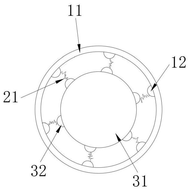
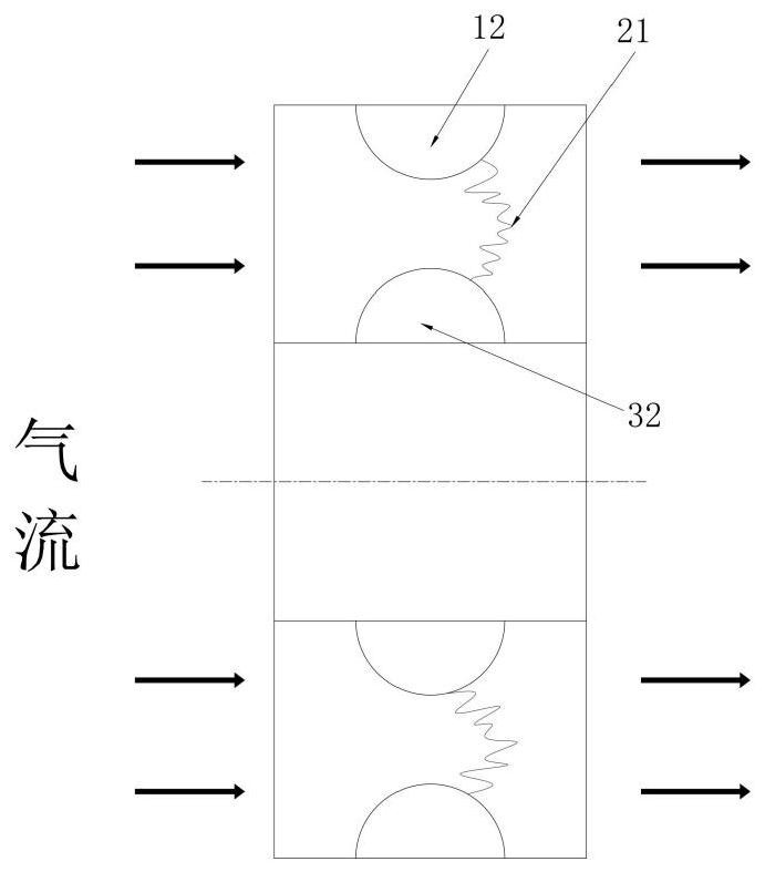
[0029] like Figure 1-2 As shown, a structure for generating a sliding arc includes a high voltage electrode seat 11 , a high voltage electrode 12 , a ground electrode seat 31 and a ground electrode 32 . Wherein, the high voltage electrode 12 and the ground electrode 32 are arranged in a ring around the ground electrode seat 31 . During operation, the high-voltage electrode 12 or the ground electrode 32 rotates around the central axis ground electrode seat 31, and at the same time, the airflow flows through the sliding arc generation area between the high-voltage electrode and the ground electrode. After a sufficient voltage is applied to the high-voltage electrode, an arc will be generated between the high-voltage electrode 12 and the ground electrode 32. Due to the existence of airflow, the arc will slide along the direction of movement of the airflow when crossing the surface of the high-voltage electrode and the surface of the low-voltage electrode. A sliding arc 21 is ge...

Embodiment 2

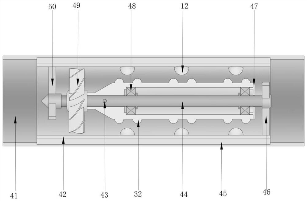
[0032] like Figure 3-7 As shown, a plasma igniter with a rotating sliding arc includes an igniter casing, one end of the igniter casing is the front incoming flow area, and the other end is the rear ignition area, and the front incoming flow area and the A structure for generating a sliding arc is provided between the fire areas at the tail, and the structure includes a grounding electrode seat installed on the central shaft, and a turbine connected to the grounding electrode seat is sleeved on the air intake end of the central shaft. The central axis of the high voltage electrode 12 is the same as that of the ground electrode 32 , and the high voltage electrode 12 is distributed in a circular array along the circumferential direction on the high voltage electrode insulating seat 42 . Each high-voltage electrode 12 is independently powered by a plasma power supply, and the high-voltage electrodes 12 are distributed in a linear array along the axial direction to ensure effecti...


PUM


Abstract

The invention discloses a structure for generating a sliding arc and a plasma igniter with the structure. The plasma igniter comprises a structure which is arranged between a front incoming flow area and a tail ignition area and used for generating the sliding arc. The structure comprises a grounding electrode base installed on a center shaft, the air inlet end of the center shaft is sleeved with a turbine connected with the grounding electrode base, a plurality of grounding electrodes protruding outwards are distributed on the grounding electrode base located in a high-voltage electrode insulating seat, and a plurality of high-voltage electrodes protruding inwards are distributed on the high-voltage electrode insulating seat; and the high-voltage electrode insulating seat is mounted on an igniter shell through an insulating jacket. A rotary sliding arc ignition mode is adopted, and effective ignition can be achieved under the extreme conditions of a high altitude and a high speed; and the structure for generating the sliding arc is matched with the turbine, it can be guaranteed that incoming flow is placed in an electric field, the discharge efficiency can be effectively improved through rotation of the grounding electrodes, it is guaranteed that the incoming flow makes full contact with the arc, and therefore the ignition success rate is increased.

Description

technical field [0001] The invention relates to the technical field of plasma ignition, in particular to a structure for generating a sliding arc and a plasma igniter with the structure. Background technique [0002] Gliding arc plasma discharge is a plasma generation method between hot plasma and cold plasma, and has the characteristics of both hot plasma and cold plasma. This feature determines that the sliding arc plasma has a relatively high temperature and can be used in fields requiring high temperature effects such as ignition and combustion; moreover, most of its energy (75% to 80%) is consumed in the non-thermal equilibrium stage, and has a large amount of energy. High-energy electrons and good chemical selectivity, so sliding arc discharge also has important application value in plasma reforming and other fields. [0003] At present, the main sliding arc plasma discharge mostly adopts blade electrode and rotating sliding arc. Among them, the blade electrode is of...

Claims


Application Information

Patent Timeline
IPC IPC(8): F02C7/266
CPCF02C7/266
Inventor 陈雷裴欢王保怀曾文程凡翀王建明
Owner SHENYANG AEROSPACE UNIVERSITY
Features
  • R&D
  • Intellectual Property
  • Life Sciences
  • Materials
  • Tech Scout
  • Unparalleled Data Quality
  • Higher Quality Content
  • 60% Fewer Hallucinations
Learn More