Pulsed eddy current detection device for thickness of stainless steel band
A technology of stainless steel strip and pulsed eddy current, applied in measuring device, electromagnetic measuring device, electromagnetic/magnetic thickness measurement, etc., can solve the problems of limiting precision manufacturing and deep processing of stainless steel strip, damaging the surface quality of stainless steel strip, and error of thickness detection accuracy, etc. Achieve wide practicability, clear use, and reduce errors
- Summary
- Abstract
- Description
- Claims
- Application Information
AI Technical Summary
Problems solved by technology
Method used
Image
Examples
Embodiment 1
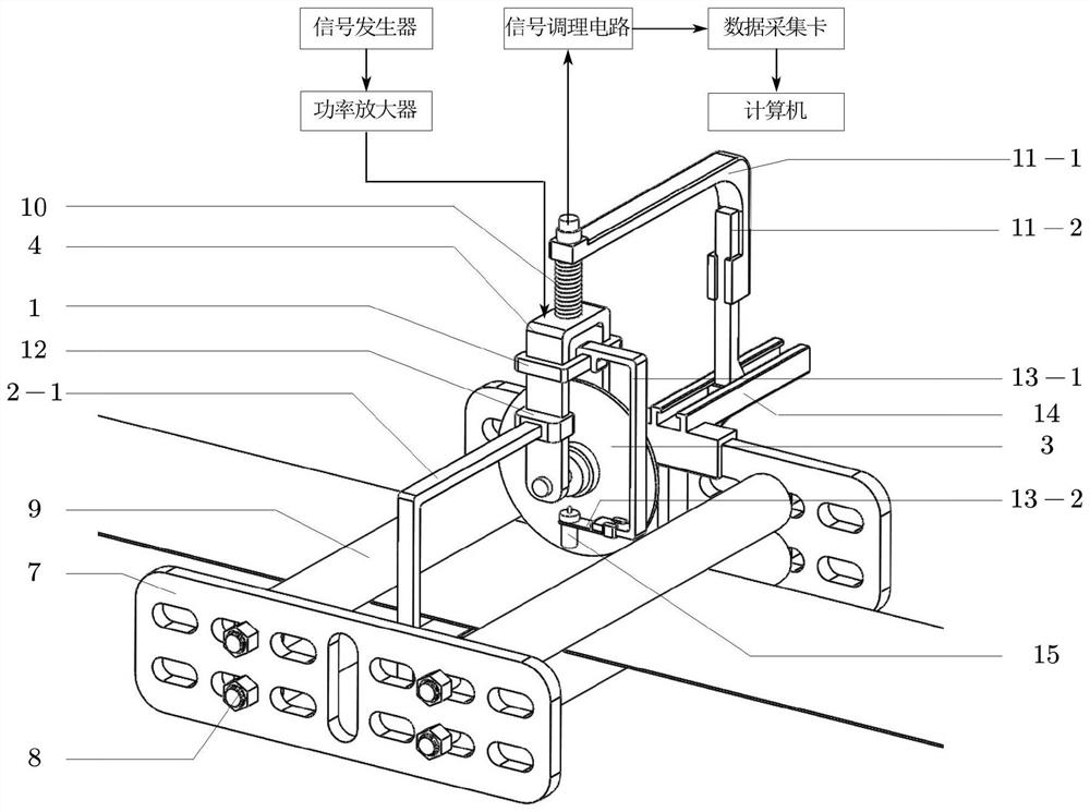
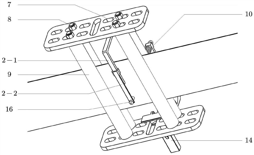
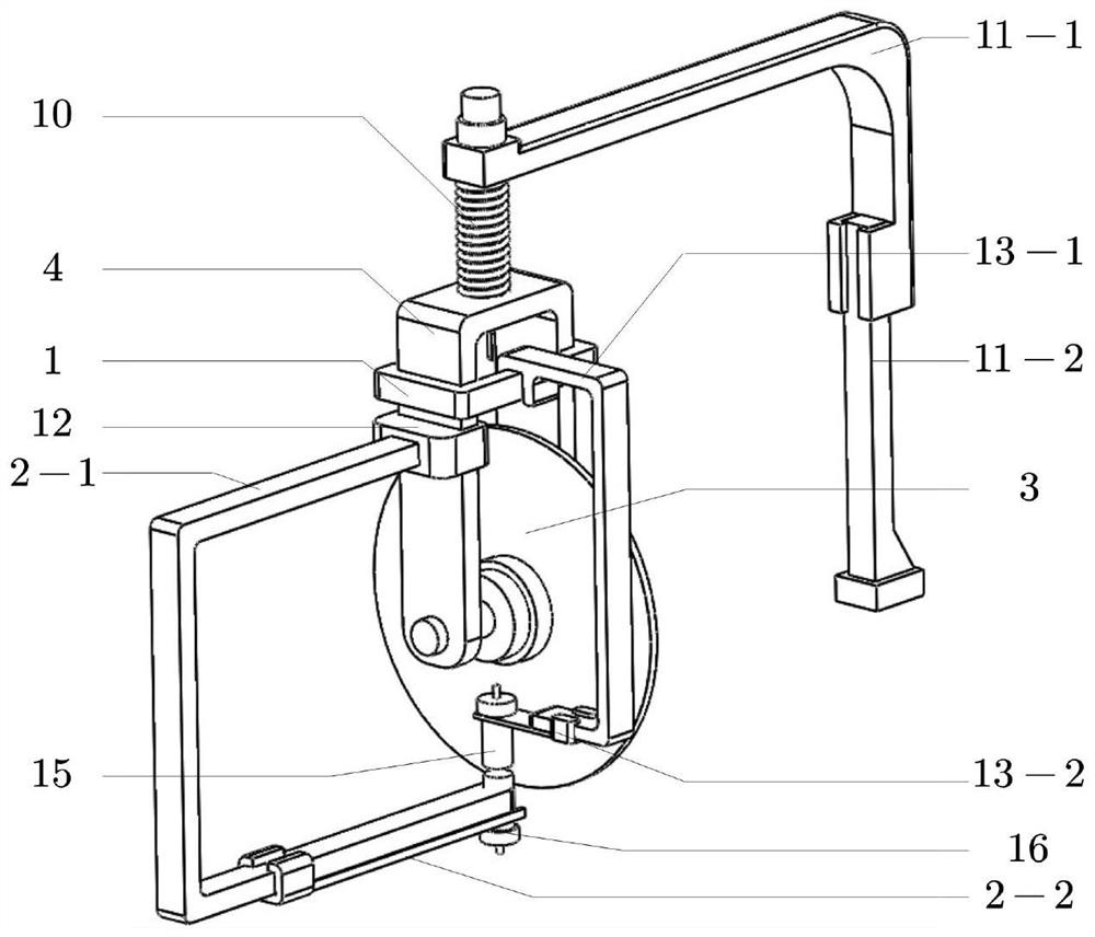
[0031] Embodiment one, as figure 1 , 2, 3, 5, 6, 7, 8 and 9, a pulsed eddy current detection device for the thickness of a stainless steel strip of the present invention includes a pulse generator, a power amplifier, a signal conditioning circuit, a data acquisition card and a computer. The eddy current detection part; also includes a pulsed eddy current detection device composed of a rolling column support plate 7, an adjustment knob 8, a rolling column 9 and a probe fixture; the rolling column 9 is four, arranged in pairs at horizontal intervals, and the The above-mentioned rolling column support plates 7 are two pieces, which are symmetrically arranged and set on both sides of the four rolling columns 9, and the described adjustment knobs 8 are arranged on the two ends of the four rolling columns 9 to play a role in fixing and Adjustment function; the rolling column support plate 7 is a multi-slotted rolling column support plate for installing multiple groups of rolling co...
Embodiment 2
[0033] Embodiment two, such as Figure 4 , 6 , Shown in 10, 12, 13 and 14, are basically the same as Embodiment 1, and the same parts are omitted. The difference is that the probe fixture includes a probe adjustment slider 1, a rolling disc 3, a roller bracket 4, a telescopic rod 10, an upper support rod 11-1 of the probe fixture, a lower support rod 11-2 of the probe fixture, and a probe Support rod 13-1, probe connecting rod 13-2, probe clamp adjustment slide rail 14 and probe 15; Installed on the support side plate 5, there are support rollers 19 in contact with the probe fixture between the rolling columns 9, and the two ends of the support rollers 19 are respectively fixed on the upper support side plate 5 via bearings 17, and the support side plate 5 Fixed on the rolling column support plate 7, the bearing tray 6 is arranged below the bearing 17, and the inner side of the supporting side plate 5 is a trapezoidal plate and is provided with positioning holes of different...
PUM
 Abstract
Description
Claims
Application Information
 - R&D
- Intellectual Property
- Life Sciences
- Materials
- Tech Scout
- Unparalleled Data Quality
- Higher Quality Content
- 60% Fewer Hallucinations
Browse by: Latest US Patents, China's latest patents, Technical Efficacy Thesaurus, Application Domain, Technology Topic, Popular Technical Reports.
© 2025 PatSnap. All rights reserved.Legal|Privacy policy|Modern Slavery Act Transparency Statement|Sitemap|About US| Contact US: help@patsnap.com


