LKB direct vibration feeding system

A feeding system and direct vibration technology, applied in the direction of electrical components, electric switches, circuits, etc., can solve the problems of high failure rate of the balance bar, reduce the installation efficiency of the balance bar of the keyboard, etc., and achieve the effect of improving the installation efficiency

Inactive Publication Date: 2022-01-11
重庆泰美自动化科技有限公司
View PDF1 Cites 0 Cited by
  • Summary
  • Abstract
  • Description
  • Claims
  • Application Information

AI Technical Summary

Problems solved by technology

[0004] The feeding mechanism of the above scheme is provided with a plurality of discharge units, and each discharge unit is set on the position of the keyboard where the balance bar is pre-installed, and each discharge unit corresponds to the balance bar at each position where the keyboard is installed; Compared with the traditional manual installation of the balance bar, the feeding mechanism of the above scheme greatly improves the installation efficiency of the balance bar; but in actual use, the feeding mechanism of the above scheme ignores some problems: during the installation process of the balance bar, the balance bar usually It needs to be placed at an optimal attitude angle (preset attitude), and the balance bar can be installed at this attitude angle to ensure the success rate of the balance bar installation to the greatest extent; therefore, in the feeding process, in addition to transporting the balance bar to the target position In addition, it is also very important to adjust the balance bar to the best installation attitude angle, but the feeding mechanism of the above scheme does not take this problem into account; it is precisely because of this problem that when the balance bar is installed with the above feeding mechanism, the balance bar The installation failure rate is extremely high, which greatly reduces the installation efficiency of the balance bar of the keyboard

Method used


Image

  • LKB direct vibration feeding system
  • LKB direct vibration feeding system
  • LKB direct vibration feeding system

Examples


Embodiment Construction

[0024] Further detailed explanation through specific implementation mode below:

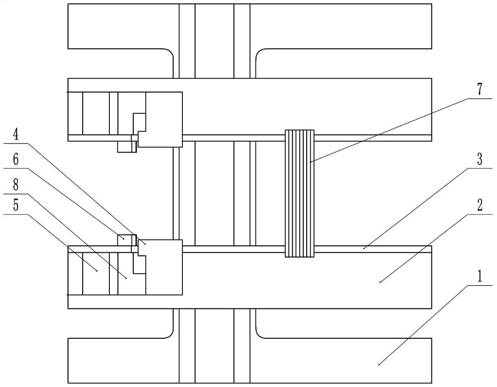
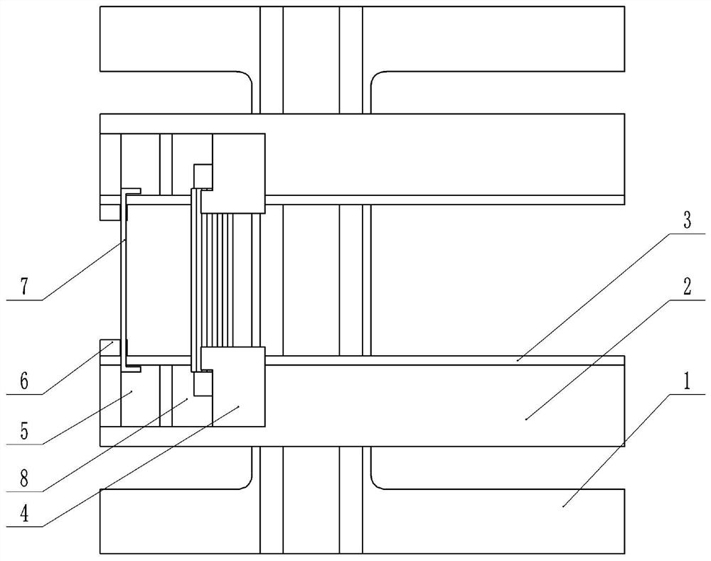
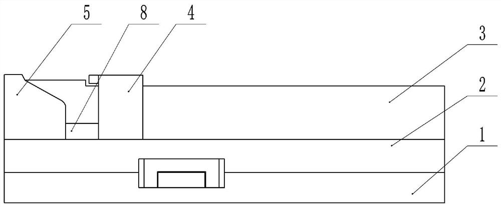
[0025] The reference signs in the accompanying drawings of the specification include: base 1 , bottom plate 2 , riser 3 , positioning seat 4 , inclined platform 5 , mounting seat 6 , balance bar 7 , and support block 8 .

[0026] The embodiment is basically as attached figure 1 , figure 2 and image 3 Shown: a LKB direct vibration feeding system, including a base 1 and two identically arranged feeding units, and the two feeding units are symmetrically arranged on the base 1. The base 1 is a base made of steel, which has a certain weight, so that it has good stability when using the feeding system of this solution.

[0027] The feeding unit includes a bottom plate 2 , a vertical plate 3 , moving parts and an inclined platform 5 . The bottom plate 2 is used to bear the weight of the structure arranged on it and provide an operation space. Riser 3 is used to hang the balance bar 7 to be instal...


PUM


Abstract

The invention belongs to the technical field of keyboard installation, and particularly relates to an LKB direct vibration feeding system. The system comprises a base and two same feeding units, and the two feeding units are symmetrically arranged on the base; the feeding unit comprises a bottom plate, a vertical plate, an inclined table and a moving part; the bottom plate is detachably arranged on the base, and the vertical plate is fixedly arranged on the bottom plate; a height difference exists between the two ends of the vertical plate, and the position of the height difference of the vertical plate is a critical position; the inclined table is fixedly arranged at the high end of the vertical plate; a preset sliding rail is arranged on the plate wall of the vertical plate, and the moving parts in the two feeding units are arranged adjacently. The system also includes a driving module used for controlling the moving parts to do reciprocating motion on the sliding rail and a vibration motor used for controlling the vibration operation of the vertical plate. According to the LKB direct vibration feeding system, the placing angle and posture of a balance rod can be adjusted.

Description

technical field [0001] The proposal belongs to the technical field of keyboard installation, and specifically relates to an LKB direct vibration feeding system. Background technique [0002] Generally speaking, most of the keys on the keyboard device are keys with square keycaps, and a small number of keys such as space key (SPACE), input key (Enter), large character key (Caps Lock), shift key (Shift), etc. The length of the keycap is greater than the width, and this type of key is called a multiple key. Because the key surface of the multiple key is long, when the user is typing on the keyboard, the finger cannot be guaranteed to hit the middle position of the keycap every time. If it is knocked on the side, it is necessary to exert greater pressure on the keycap to trigger the key. Therefore, it is necessary to add a balance bar so that the keycap will not tilt up and down due to the difference in the force point. The two ends of the keycap achieve a balanced effect, and ...

Claims


Application Information

Patent Timeline
Patent Type & Authority Applications(China)
IPC IPC(8): H01H13/88H01H13/7065H01H11/00
CPCH01H13/88H01H13/7065H01H11/00
Inventor 刘春华
Owner 重庆泰美自动化科技有限公司
Why Eureka
Try Eureka