
Special efficient deicing device for cable

A cable and high-efficiency technology, which is applied in the field of high-efficiency deicing devices for cables, can solve the problems of high-voltage cables sinking, time-consuming, labor-intensive, and dangerous.

Active Publication Date: 2022-01-11
CHONGQING ELECTRIC POWER COLLEGE
View PDF7 Cites 0 Cited by
  • Summary
  • Abstract
  • Description
  • Claims
  • Application Information

AI Technical Summary

Problems solved by technology

When the ice coating reaches a certain thickness, the weight of the ice coating plus the weight of the high-voltage cable will cause the high-voltage cable to sink, collapse, and break, which will affect power transmission
In addition, when high-voltage cable maintenance, wiring, overhaul and other operations are required, the ice layer on the high-voltage cable will also affect the normal construction
Traditional deicing methods generally use fire, blasting, etc., which are extremely dangerous and easy to damage cables, with low deicing efficiency and high risk factors
A Chinese invention patent named arc hammer for cable deicing and patent number ZL201110103871.2 discloses a special arc hammer for cable deicing. The hammer body consists of a vertical section and an arc section. The straight section is connected to the middle of the outer side of the arc section, and the cross-section of the hammer body is square, and the angle between the inner sides of the arc section is a semicircle angle, the diameter of the semicircle angle is larger than the diameter of the cable, and the top of the vertical section There are multiple cones fixed, and the handle is fixed on the vertical section of the arc-shaped hammer. This manual deicing mechanism requires workers to hold the ice in their hands. This method is time-consuming and laborious, and the efficiency is extremely low.

Method used


Image

  • Special efficient deicing device for cable
  • Special efficient deicing device for cable
  • Special efficient deicing device for cable

Examples


Embodiment Construction

[0031] In order to make the purpose, technical solution and advantages of the present application clearer, the technical solution of the present application will be clearly and completely described below in conjunction with specific embodiments of the present application and corresponding drawings. Apparently, the described embodiments are only some of the embodiments of the present application, rather than all the embodiments. Based on the embodiments in this application, all other embodiments obtained by persons of ordinary skill in the art without making creative efforts belong to the scope of protection of this application.

[0032] It should be noted that when an element is referred to as being “fixed” to another element, it can be directly on the other element or there can also be an intervening element. When an element is referred to as being "connected to" another element, it can be directly connected to the other element or intervening elements may also be present.

...


PUM


Abstract

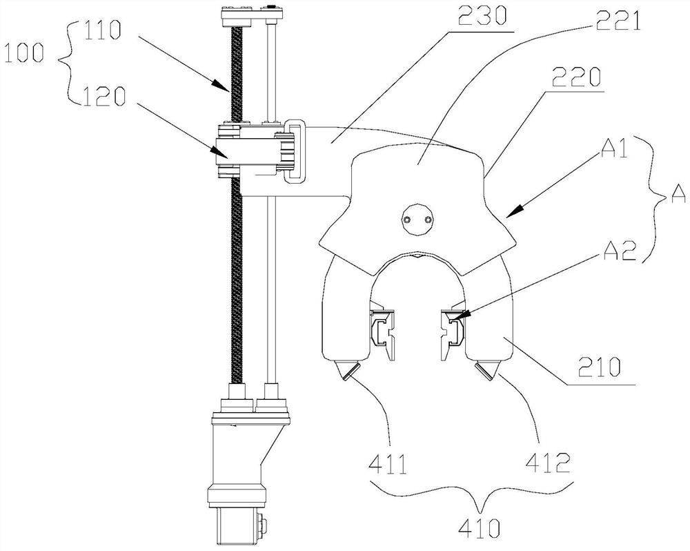
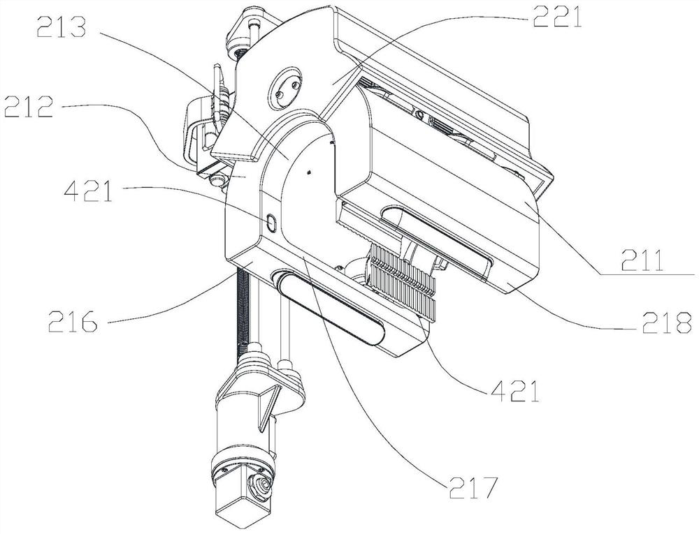
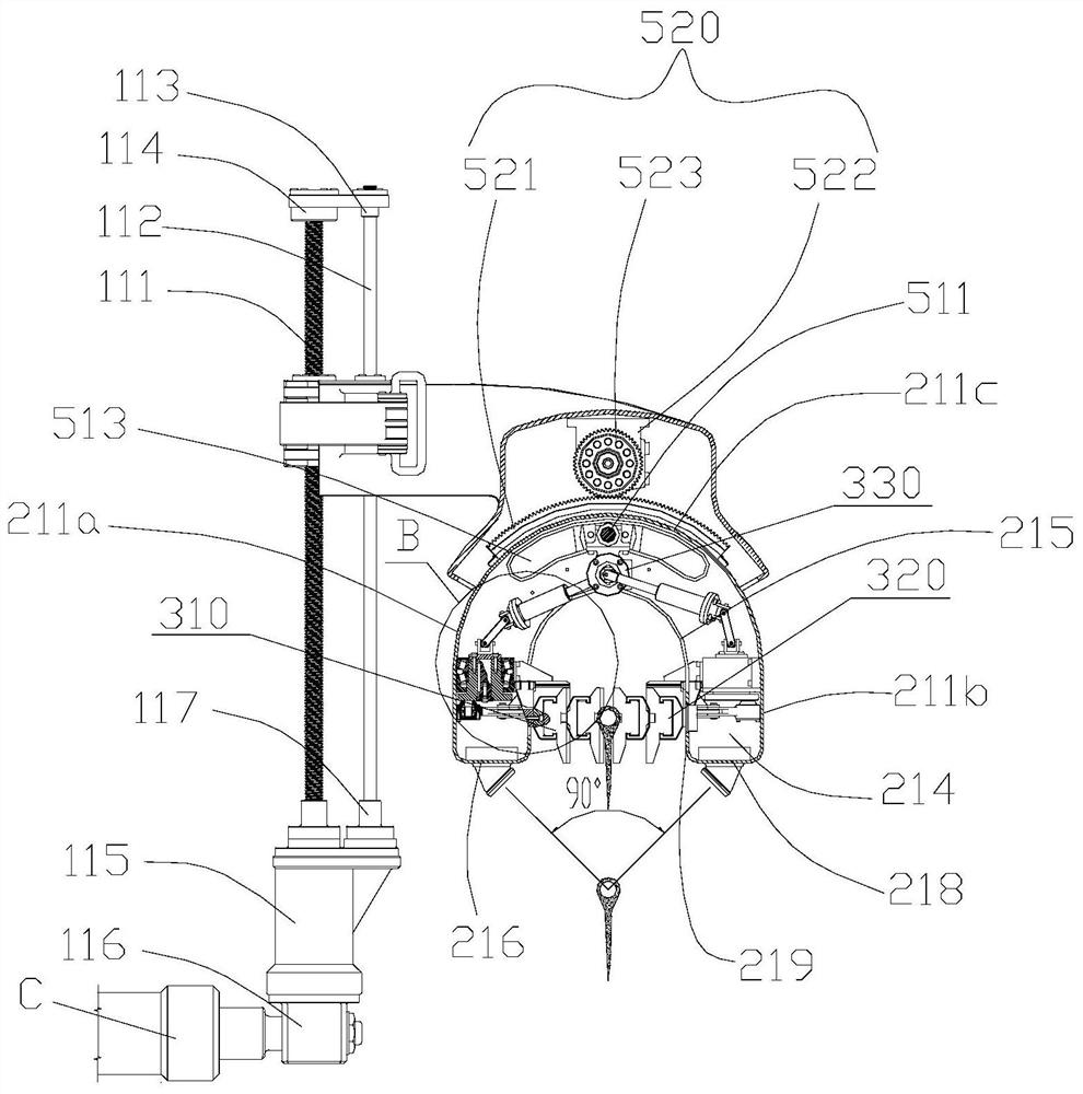
The invention discloses a special efficient deicing device for a cable. The device comprises a lifting mechanism and a deicing mechanism slidably mounted on the lifting mechanism, and is characterized in that the lifting mechanism comprises a lifting rod group and a mounting assembly in sliding fit with the lifting rod group; the deicing mechanism comprises an outer cover assembly and a deicing manipulator arranged in the outer cover assembly; the outer cover assembly comprises a mounting cover and a connecting cover covering the outer cover surface of the mounting cover, and a connecting arm connected with the mounting assembly is formed at the side, facing the mounting assembly, of the connecting cover; the mounting cover is provided with a first side cover part, a second side cover part and a top cover part, wherein the first side cover part and the second side cover part are oppositely arranged, and the top cover part is formed between the top ends of the first side cover part and the second side cover part; the deicing manipulator comprises a first hammer body formed at the inner side position of the first side cover part, a second hammer body formed at the inner side position of the second side cover part, and a driving mechanism for driving the first hammer body and the second hammer body to move in the opposite directions and reset.

Description

technical field [0001] The present application relates to the field of cable deicing, in particular to a high-efficiency deicing device dedicated to cables. Background technique [0002] In the cold winter season, freezing rain and snowfall occur all over the country. Once there is freezing rain and snowfall, it will cover the high-voltage cables and gather to form ice. When the ice coating reaches a certain thickness, the weight of the ice coating plus the weight of the high-voltage cable will cause the high-voltage cable to sink, collapse, and break, which will affect power transmission. In addition, when operations such as maintenance, wiring, and repair of high-voltage cables are required, the ice layer on the high-voltage cables will also affect normal construction. Traditional deicing methods generally use methods such as fire and blasting. This method is extremely dangerous, and it is easy to damage the cables. The deicing efficiency is low and the risk factor is hi...

Claims


Application Information

Patent Timeline
IPC IPC(8): H02G7/16B08B7/02
CPCH02G7/16B08B7/02Y02E10/72
Inventor 欧儒春向鹏陈绍敏李江涛向贤兵姚昌模曾小义唐前辉张友利谢德勇陈颖罗远福鲁冠军黄丹陈晓余向上张大伟梅其政刘建国高倩霞王磊吴华兵聂思宇雷利斌赵兴赵鑫孙正圆王康宁蒋金陶谭龙伟柳帅黄瀛周姜宇航董长昊徐昇邵龙黄平直高鹏徐文浩徐瑶赖福晴吴镝文柯奥王茂王一斌岩轰罕司嘉威吴至豪李欣棋李欣潞向平
Owner CHONGQING ELECTRIC POWER COLLEGE
Learn More