Wiping device used after wafer cleaning

A post-cleaning, wafer technology, used in cleaning methods and utensils, removing smoke and dust, cleaning flexible objects, etc., can solve the problems of inability to ensure the cleanliness of wafer wiping, no two-way blowing and suction, and reducing airflow utilization. The effect of avoiding physical contact wiping, saving power and improving utilization

Inactive Publication Date: 2022-01-14
JIANGSU ASIA ELECTRONICS TECH CO LTD
View PDF0 Cites 0 Cited by
  • Summary
  • Abstract
  • Description
  • Claims
  • Application Information

AI Technical Summary

Problems solved by technology

[0003] However, in the prior art, the wiping device is used after the wafer is cleaned: 1. There is no bidirectional function of blowing and suction, and the control of the water liquid is weak, and the cleanliness of the wafer wiping cannot be guaranteed; 2. There is no setting for air-flow wiping, which requires Wiping with physical contact increases the dust attached to the surface of the wafer; 3. There is no setting for air circulation, which requires additional power and reduces the utilization of air flow

Method used


Image

  • Wiping device used after wafer cleaning
  • Wiping device used after wafer cleaning
  • Wiping device used after wafer cleaning

Examples


Embodiment 1

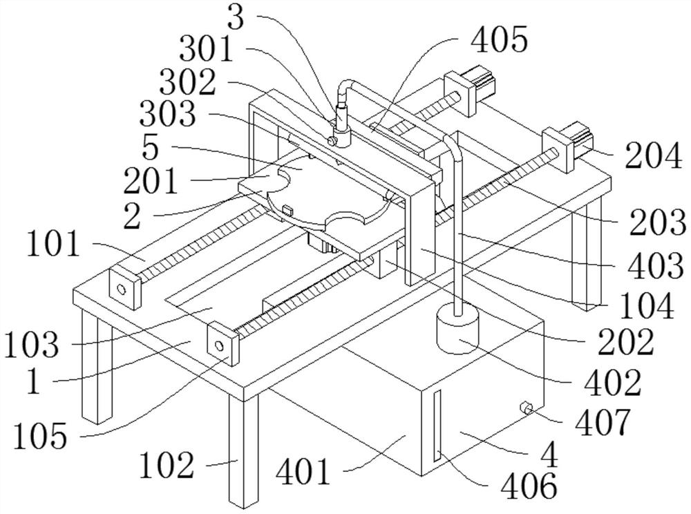
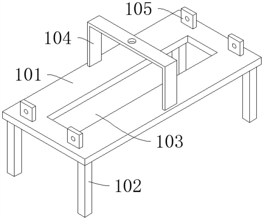
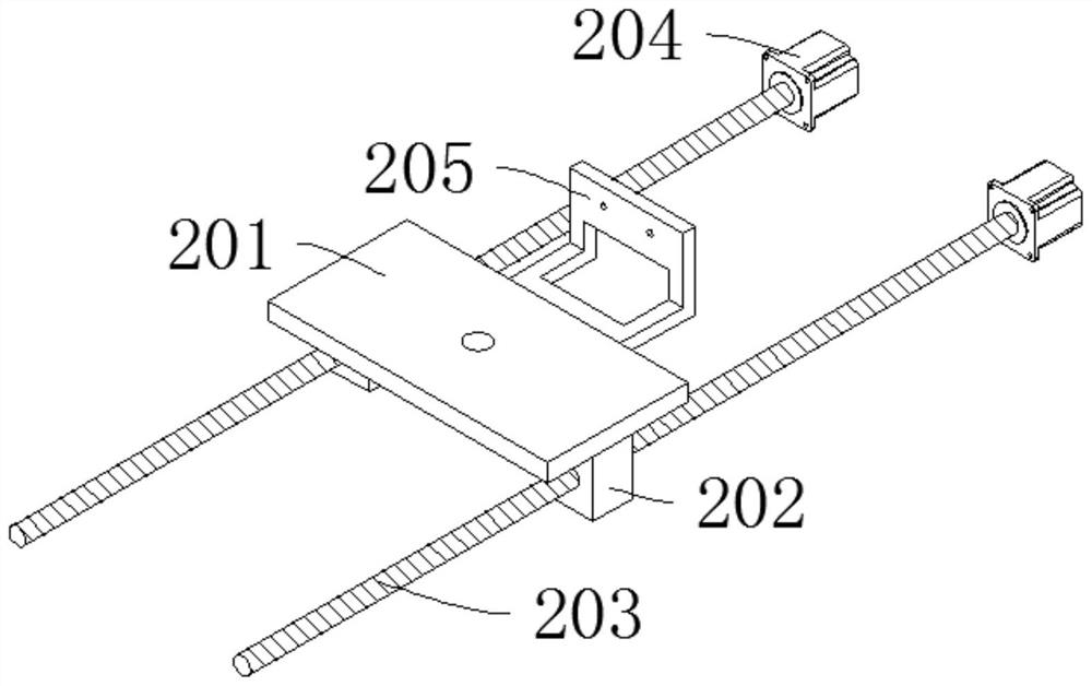
[0045] Such as Figure 1-Figure 7As shown, a wiping device after wafer cleaning includes a rack device 1 for support, and a translation device 2 for reciprocating movement. A clamping device 5 for fixing the rotation of the wafer is installed on the translation device 2 , the rack device 1 is equipped with an air spray device 3 for spraying air to wipe the surface of the wafer, and the rack device 1 is provided with a circulation device 4 for sucking air and water droplets below the rack device 1; Four support legs 102 are evenly distributed at the four corners of the bottom, four support plates 105 are evenly distributed at the four corners of the support platform 101, an avoidance groove 103 is arranged in the middle of the support platform 101, and a fixed frame 104 is arranged above the avoidance groove 103; Plate 201, two nut blocks 202 are symmetrically installed on the bottom of the supporting plate 201, a lead screw 203 is installed in the middle of the screw block 202...

Embodiment 2

[0048] Such as Figure 8 As shown, the difference between Embodiment 2 and Embodiment 1 is that the clamping device 5 includes a second motor 501, a swivel frame 505 is installed on the second motor 501, three clamping plates 503 are evenly distributed on the circumference of the swivel frame 505, and the swivel frame 505 The bottom plate is provided with a connecting sleeve 506, and the second motor 501 drives the swivel frame 505 through the connecting sleeve 506 to fix the wafer to rotate through the clamping plate 503; the connecting sleeve 506 and the rotary frame 505 are welded together, and the clamping plate 503 and the rotary frame 505 are riveted together. Welding ensures that the connecting sleeve 506 is strong and firm, and riveting ensures that the clamping plate 503 is stable and reliable.

[0049] Working principle: slide the T-shaped tube 303 up and down in the support sleeve 301, adjust the height of the nozzle 304, and tighten the locking nail 302 to fix it, ...


PUM


Abstract

The invention discloses a wiping device used after wafer cleaning. The wiping device comprises a rack device used for supporting, and further comprises a translation device used for reciprocating motion, wherein a clamping device used for fixing wafer rotation is installed on the translation device, an air injection device used for injecting air to wipe the surface of a wafer is installed on the rack device, a circulating device for sucking air and water drops is arranged below the rack device, the rack device comprises a supporting table, four supporting legs are evenly distributed at the four corners of the bottom of the supporting table, four supporting plates are evenly distributed at the four corners of the supporting table, and an avoiding groove is formed in the middle of the supporting table. According to the wiping device, through arrangement of blowing and suction bidirectional effects, the control of water liquid is enhanced, the cleanliness of wafer wiping is ensured, through arrangement of airflow wiping, physical contact wiping is avoided, dust attached to the surface of the wafer is reduced, and through arrangement of airflow circulation, power is saved, the utilization rate of airflow is increased.

Description

technical field [0001] The invention relates to the technical field of wafer cleaning, in particular to a wiping device for wafer cleaning. Background technique [0002] Wafer cleaning is a process of removing pollutants generated by contact with various organic substances, particles and metals during the continuous processing, shaping and polishing of wafers. It is an important process step in the wafer manufacturing process. After the wafer is cleaned, the water must be completely wiped clean for subsequent processing. . [0003] However, in the prior art, the wiping device is used after the wafer is cleaned: 1. There is no bidirectional function of blowing and suction, and the control of the water liquid is weak, and the cleanliness of the wafer wiping cannot be guaranteed; 2. There is no setting for air-flow wiping, which requires Wiping with physical contact increases the dust attached to the surface of the wafer; 3. There is no setting for air circulation, which req...

Claims


Application Information

Patent Timeline
IPC IPC(8): B08B5/02B08B11/02B08B15/00
CPCB08B5/023B08B11/02B08B15/007
Inventor 钱诚李刚王禹涵
Owner JIANGSU ASIA ELECTRONICS TECH CO LTD
Why Eureka
Try Eureka