Pipe fitting cutting and transporting device

A technology for transportation devices and pipe fittings, which is applied in the field of pipe cutting technology and equipment, can solve problems such as damage to the surface of pipe fittings, troublesome and unreasonable overall processes, and achieve good buffering effects, avoid bump damage, and improve functionality and practicability.

Pending Publication Date: 2022-01-14
无锡水登机械有限公司
View PDF0 Cites 0 Cited by
  • Summary
  • Abstract
  • Description
  • Claims
  • Application Information

AI Technical Summary

Problems solved by technology

[0002] In the prior art, in the laser pipe cutting mechanism, the pipe fittings need to be placed at the specified position after being cut. In the existing cutting mechanism, tooling for blanking is usually set up, and the cut pipe fittings are placed on the tooling. The overall process is very cumbersome and cumbersome, and not convenient enough to put it on the transportation tool, and then transfer it to the designated location for storage. In addition, if the pipe fittings fall too high during the cutting process, they will be damaged accordingly. Knocking into the pipe fittings will damage the surface of the pipe fittings accordingly, which is also very unreasonable.

Method used


Image

  • Pipe fitting cutting and transporting device
  • Pipe fitting cutting and transporting device
  • Pipe fitting cutting and transporting device

Examples


Embodiment Construction

[0026] In order to further explain the technical means and effects of the present invention to achieve the intended purpose of the invention, the specific implementation, structure, features and effects of the present invention will be described in detail below in conjunction with the accompanying drawings and preferred embodiments.

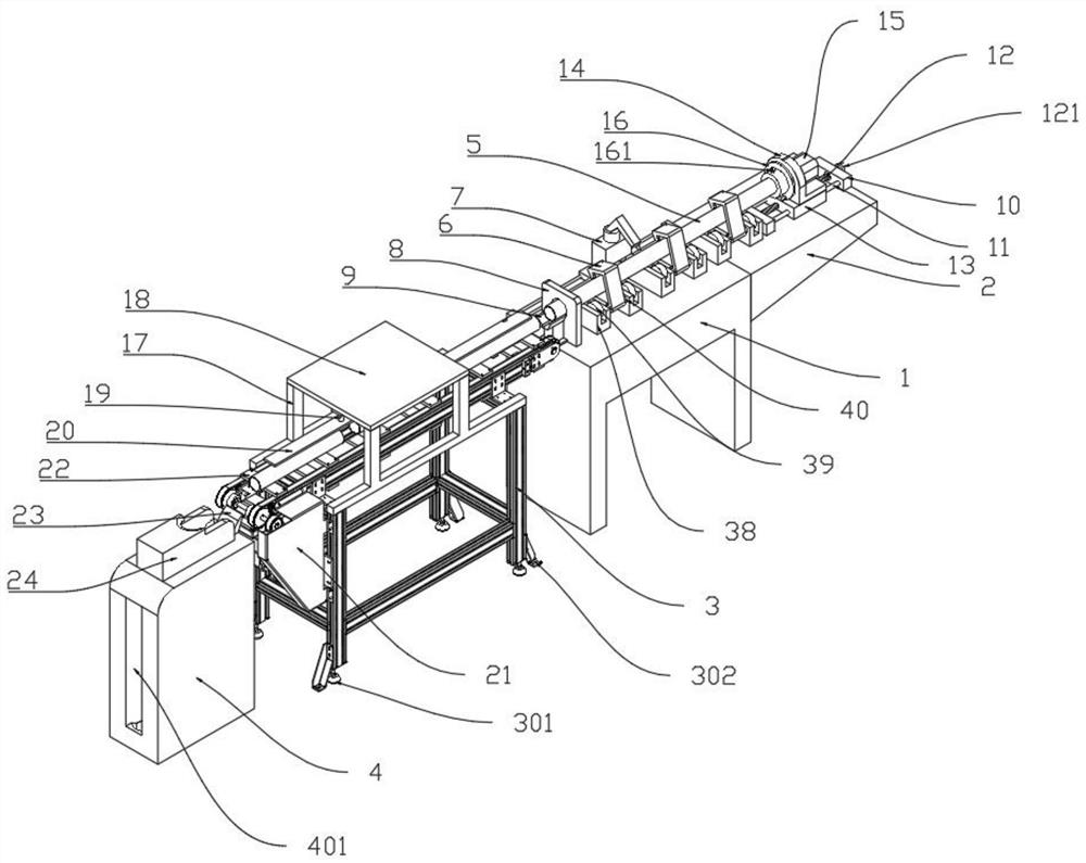
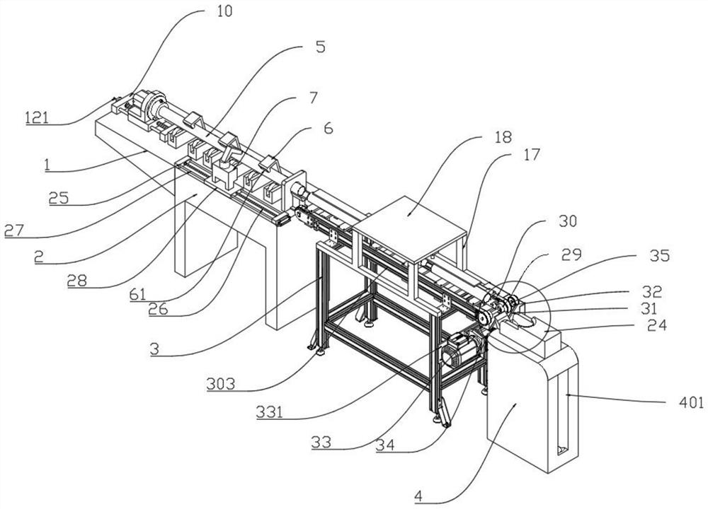
[0027] see Figure 1 to Figure 7, a pipe cutting and transporting device provided by the present invention includes a cutting table 1, an adjusting table 2 is provided on one side of the cutting table 1, and a first sliding assembly is arranged on the adjusting table 2, and the first sliding assembly includes a first screw rod 12, The two ends of the first screw mandrel 12 are movably connected on the first adjusting plate 10 through bearings, and the outer side of the first adjusting plate 10 is provided with a disc handle 121, and the disc handle 121 is assembled on one end of the first screw mandrel 12, and the first screw mandrel 12 Both side...


PUM


Abstract

The invention discloses a pipe fitting cutting and transporting device, which comprises a cutting table; an adjusting table is arranged on one side of the cutting table; an adjustable clamping mechanism is arranged on the adjusting table; a pipe fitting is clamped on the clamping mechanism; a rotary supporting mechanism is arranged below the pipe fitting; a movable laser cutting machine is arranged on the cutting table; a positioning plate is arranged on the cutting table; a through hole matched with the pipe fitting is arranged in the positioning plate; a pipe frame is arranged on one side of the positioning plate; a conveying frame is arranged on the other side of the cutting table; two symmetrically-distributed guide rails are arranged at the top of the conveying frame; conveying wheels are installed at the two ends of the guide rails; conveying chain plates are installed on the conveying wheels; lining plates are connected to the conveying chain plates through bolts; driving shafts are assembled in the conveying wheels; and one end of each driving shaft is connected with a driving device of which one side is provided with a receiving mechanism. Compared with the prior art, collection of cut pipe fittings can be effectively guaranteed, the situation that the cut pipe fittings directly fall to the ground and are damaged after being cut is avoided, the production quality of the pipe fittings is greatly improved, the labor cost is reduced, and the production efficiency is improved.

Description

technical field [0001] The invention belongs to the technical equipment field of pipe fitting cutting, and in particular relates to a pipe fitting cutting transportation device. Background technique [0002] In the prior art, in the laser pipe cutting mechanism, the pipe fittings need to be placed at the specified position after being cut. In the existing cutting mechanism, tooling for blanking is usually set up, and the cut pipe fittings are placed on the tooling. The overall process is very cumbersome and cumbersome, and not convenient enough to put it on the transportation tool, and then transfer it to the designated location for storage. In addition, if the pipe fittings fall too high during the cutting process, they will be damaged accordingly. Knocking into the pipe fittings will damage the surface of the pipe fittings accordingly, which is also very unreasonable during transportation. Contents of the invention [0003] The purpose of the present invention is to pro...

Claims


Application Information

Patent Timeline
Patent Type & Authority Applications(China)
IPC IPC(8): B23K26/38B23K26/70
CPCB23K26/38B23K26/702
Inventor 李桓
Owner 无锡水登机械有限公司
Why Eureka
Try Eureka