Intelligent welding device and method for wind power stator core

A stator core and welding device technology, applied in auxiliary devices, welding equipment, welding equipment, etc., can solve the problems of poor welding effect, reduced penetration depth, and low intelligence, so as to avoid the reduction of penetration depth and scientific method design , to meet the effect of continuous welding

Active Publication Date: 2022-01-14
CHANGZHOU SHENLI MOTOR
View PDF11 Cites 3 Cited by
  • Summary
  • Abstract
  • Description
  • Claims
  • Application Information

AI Technical Summary

Problems solved by technology

[0004] However, there are deficiencies in the stator core welding machine. First, it is only suitable for the welding process of the segmented stator core, not for the welding process of the laminated stator core; the second is that it adopts a vertical welding process. Its own defects will lead to lower penetration and poor welding effect; third, it does not have automatic loading and unloading functions, and its intelligence is low, which cannot meet the needs of continuous welding, and the welding efficiency needs to be improved

Method used


Image

  • Intelligent welding device and method for wind power stator core
  • Intelligent welding device and method for wind power stator core
  • Intelligent welding device and method for wind power stator core

Examples


Embodiment 1

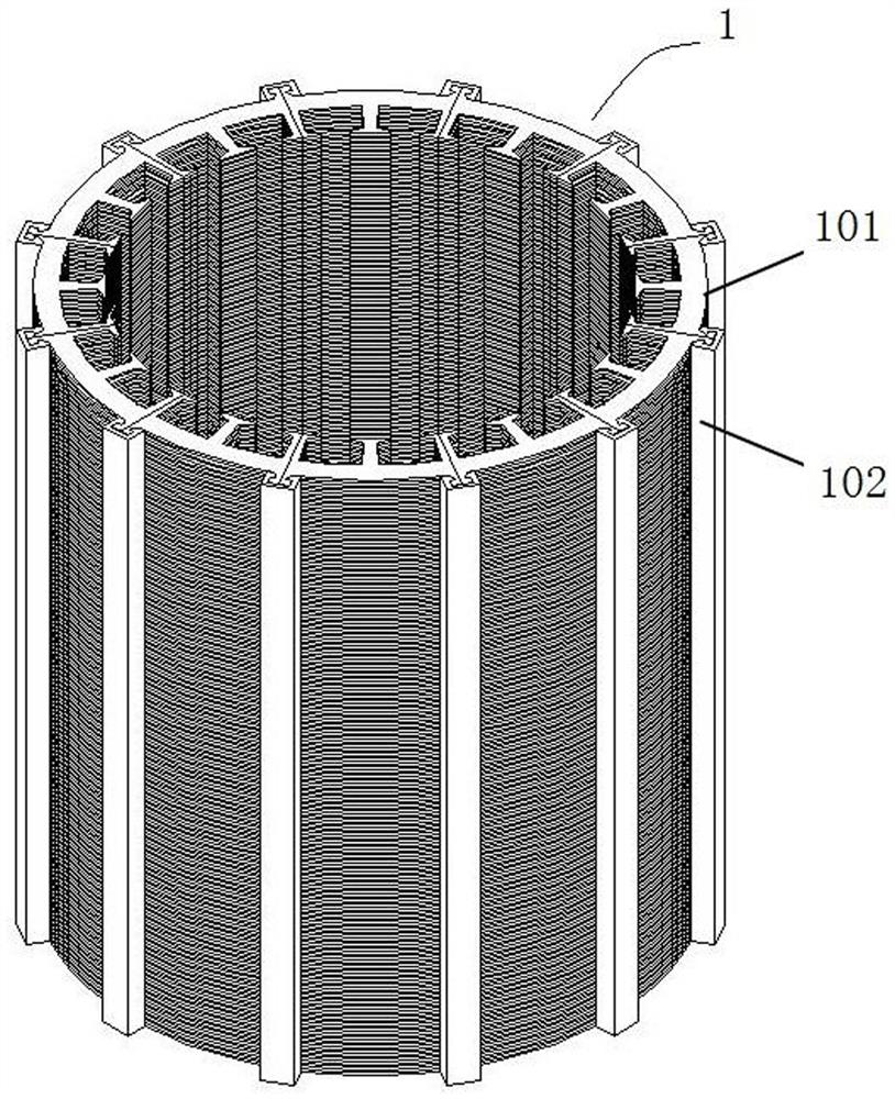
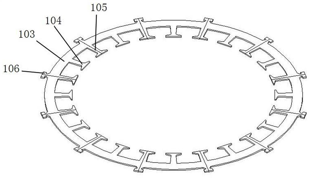
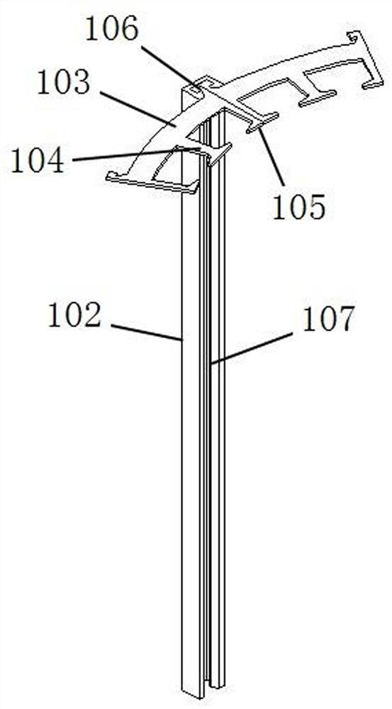
[0042] This embodiment is an intelligent welding device for a wind power stator core, which is used for welding the segmented laminated stator core 1, such as Figure 1-Figure 3 As shown, the segmented laminated stator core 1 is composed of several layers of segmented laminations 101 distributed in a circular array and locking strips 102 for fixing the segmented laminations 101 in circles. The block lamination 101 includes an arc-shaped sheet body 103, at least one complete winding board 104 is provided at the inner middle of the arc-shaped sheet body 103, and semi-complete winding boards 105 are provided at both ends of the inner side. The semi-complete winding boards of two adjacent arc-shaped sheets 103 can be assembled into a complete winding board; the outer two ends of the arc-shaped sheets 103 are provided with semi-complete locking plates 106, and the two adjacent arc-shaped sheets The semi-complete lock plate 106 of 103 can be assembled into a complete lock plate. Th...

Embodiment 2

[0051] The structure and application of this embodiment are basically the same as those of Embodiment 1, and the differences are as follows: Figure 11 As shown, the round mounting column 9 and the retaining ring 10 are locked in position through threaded socketing. Specifically, an external thread groove 904 can be provided on the outer surface of the cylinder part 901, and an internal thread part can be added inside the retaining ring 10 to realize position locking. . In order to facilitate manual rotation of the retaining ring 10, a handle can be added on its outside.

Embodiment 3

[0053] The structure and application of this embodiment are basically the same as those of Embodiment 1, and the differences are as follows: Figure 12 As shown, the round mounting column 9 and the retaining ring 10 are locked in position by screw locking. Specifically, a number of fastening screws 15 can be threaded through the retaining ring 10, and the fastening screws 15 are screwed inward to the cylinder part 901. The unslotted position offsets to achieve position locking. The position locking principle of this embodiment is similar to that of Embodiment 1, which uses the friction resistance between the fastening screw 15 and the round mounting column 9 to replace the friction resistance between the round mounting column 9 and the stop ring 10 in Embodiment 1 . A loose fit is adopted between the round mounting column 9 and the retaining ring 10, and the position between the two can be adjusted freely before the fastening screw 15 is locked.


PUM


Abstract

The invention belongs to the technical field of wind driven generators, and particularly relates to an intelligent welding device and method. The welding device comprises a guide rail base plate, two guide rails, sliding blocks, fixing supports, an overturning support, an overturning motor, a mounting disc, a splicing circle mounting column, a baffle ring, a transposition motor and a welding cabinet, wherein the two guide rails are fixedly mounted at the upper end of the guide rail base plate, sliding blocks are installed on the guide rails, fixing supports are fixed to the upper ends of the sliding blocks, the overturning support is rotationally supported between the two fixing supports, the overturning motor is installed on one fixing support, the mounting disc is fixed to the outer side of the overturning support, the transposition motor is fixed to the inner side of the overturning support, the baffle ring is installed on the splicing circle mounting column, and the welding cabinet is provided with an electric roller shutter and a welding mechanism. The device is high in intelligent degree and suitable for welding machining of a block laminated stator iron core, the conveying assembly and the welding mechanism are reasonable in design, and welding machining of the upper end face, the lower end face and the circumferential face of the iron core can be achieved through cooperation of the conveying assembly and the welding mechanism.

Description

technical field [0001] The invention belongs to the technical field of wind power generators, and in particular relates to a wind power stator core intelligent welding device and method. Background technique [0002] The stator core is an important part of the wind turbine. Its main function is to form a closed loop with the magnetic induction lines generated by the rotor when it is in the power generation state, and the electromagnetic wires wound in the tooth slots of the stator core cut the magnetic induction generated by the rotor. wire, thereby generating an induced current in the magnet wire. The stator core consists of integral, block, laminated and other structures. Among them, the laminated stator core is generally made of silicon steel sheets. The power loss in the generator includes "hysteresis loss" and "eddy current loss". The hysteresis loop of silicon steel is narrow, and using it as a stator core can reduce hysteresis loss and greatly reduce heat generatio...

Claims


Application Information

Patent Timeline
Patent Type & Authority Applications(China)
IPC IPC(8): B23K31/02B23K37/047
CPCB23K31/02B23K37/047
Inventor 陈猛张兵赵恒
Owner CHANGZHOU SHENLI MOTOR
Why Eureka
Try Eureka