Feeding and discharging mechanism

A technology of pushing mechanism and feeding mechanism, which is applied to conveyors, vibrating conveyors, conveyor objects, etc., can solve the problems of low degree of automation, low work efficiency, and manpower consumption, so as to improve the degree of automation, improve efficiency, The effect of liberating manpower

Pending Publication Date: 2022-01-14
华天科技(宝鸡)有限公司
View PDF7 Cites 0 Cited by
  • Summary
  • Abstract
  • Description
  • Claims
  • Application Information

AI Technical Summary

Problems solved by technology

[0003] In order to solve the problems existing in the prior art, the object of the present invention is to provide a loading and unloading mechanism to solve the problems of manpower consumption, low work efficiency, inconvenient operation and low degree of automation in the existing traditional manual discharge process. question

Method used


Image

  • Feeding and discharging mechanism
  • Feeding and discharging mechanism
  • Feeding and discharging mechanism

Examples


Embodiment 1

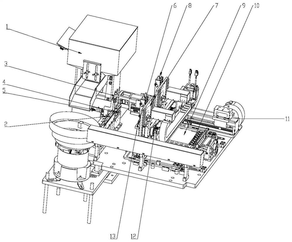
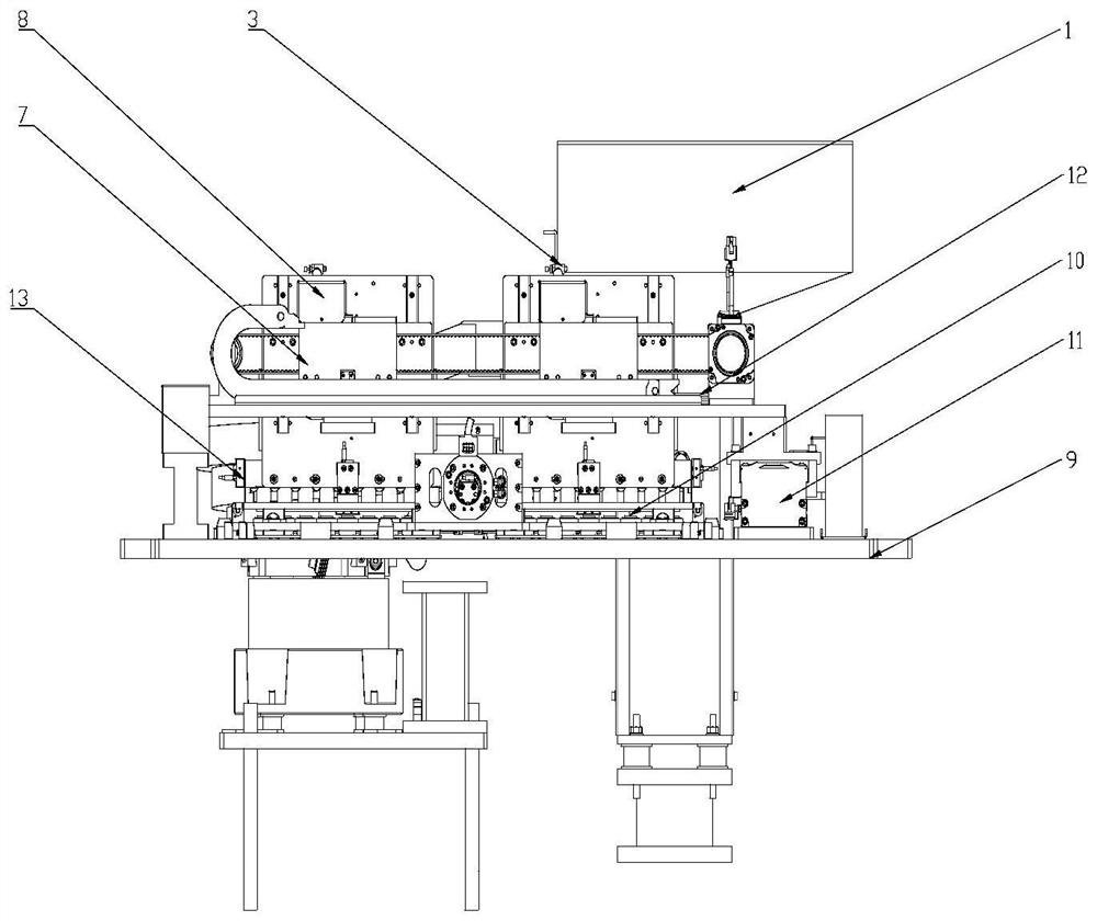
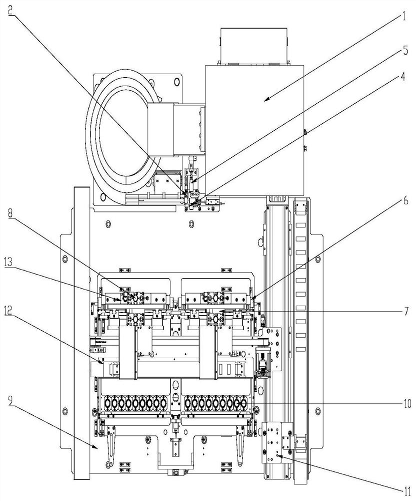
[0037]The present invention provides a loading and unloading mechanism, including a fixing mechanism, a feeding mechanism and a material receiving mechanism; the fixing mechanism includes a fixed large plate 9 and a cake rack 10, and the vibrating plate mechanism includes a feeding bin, a direct vibration guide rail and Circular silo, the setting of the feed silo needs to have a certain radian, which can effectively help the mechanism to transmit smoothly during transmission, and effectively reduce the possibility of material jamming. In this embodiment, circular feed is used The bin is only used as a preferred embodiment. This mechanism can also be provided with a plurality of feeding bins, and other feeding bins are arranged above the circular feeding bin. The bottom of the feeding bin and the circular feeding bin is connected with a vibration body. The discharge port of the circular silo is connected with a direct vibration guide rail, one side of the end of the direct vibra...

Embodiment 2

[0039] Such as figure 1 As shown, an automatic upper and lower plastic sealing material mechanism provided by the present invention includes a vibrating plate mechanism, a material receiving mechanism, a material pushing mechanism, a material receiving and transferring mechanism, a material unloading mechanism, a fixed large plate, and a material cake rack. Set at least one, one of which is a circular feeding bin; the circular feeding bin is located directly below the outlet of the other feeding bins, and the direct vibration guide rail is connected with the circular feeding bin; the material receiving mechanism 2 is connected with the direct vibration The guide rail is connected and adjacent to the pushing mechanism 5, and the in-position detection sensor 3 is connected with the pushing mechanism 5 and placed directly above the material receiving mechanism 2; The feeding mechanism 2 is connected; the fixed large plate 9 is fixed and installed on the frame of the box body by s...


PUM


Abstract

The invention discloses a feeding and discharging mechanism which comprises a fixing mechanism, a feeding mechanism and a material receiving mechanism. The feeding mechanism comprises a vibration body, a feeding bin, a material bearing mechanism and a material pushing mechanism, the vibration body is connected with the feeding bin, a direct vibration guide rail is arranged at a discharging opening of the feeding bin, the tail end of the direct vibration guide rail is connected with the material bearing mechanism, the material pushing mechanism is arranged at the position adjacent to the material bearing mechanism, a discharging port of the material bearing mechanism is connected with a feeding port of the material pushing mechanism, the material pushing mechanism and the material bearing mechanism are horizontally arranged, a material receiving mechanism is arranged at the tail end of a material pushing position of the material pushing mechanism, a material cake frame is arranged below the material receiving mechanism, and the material cake frame is arranged on the fixing mechanism. By means of the mechanism, automation of the whole feeding and discharging process can be achieved during discharging of equipment, the utilization rate, the discharging efficiency and the production efficiency of the equipment are improved to a great extent, and manpower consumption is greatly reduced.

Description

technical field [0001] The invention relates to a loading and unloading mechanism for multiple cake arrangements, and is particularly suitable for loading and unloading procedures in various integrated circuit packaging and testing industries. Background technique [0002] In the field of discharging cakes in the plastic packaging process of the integrated circuit packaging industry, manual cake discharging is mainly used in China for feeding cakes. When manual discharging is used, it takes a long time to discharge cakes, and the work efficiency is low. , Occupying a large amount of human productivity, at the same time, the labor intensity is high, and the automation of the work process cannot be realized. Contents of the invention [0003] In order to solve the problems existing in the prior art, the object of the present invention is to provide a loading and unloading mechanism to solve the problems of manpower consumption, low work efficiency, inconvenient operation and...

Claims


Application Information

Patent Timeline
Patent Type & Authority Applications(China)
IPC IPC(8): B65G47/82B65G47/88B65G27/02
CPCB65G47/82B65G47/88B65G27/02
Inventor 葸文斌刘宁
Owner 华天科技(宝鸡)有限公司
Why Eureka
Try Eureka