Warp knitting machine
A technology of warp knitting machine and transmission mechanism, applied in the field of warp knitting machine
- Summary
- Abstract
- Description
- Claims
- Application Information
AI Technical Summary
Problems solved by technology
Method used
Image
Examples
Embodiment Construction
[0027] figure 1 A warp knitting machine 1 with a needle bed 2 is shown in very schematic form. The warp knitting machine 1 has a plurality of bars, not further shown, each of which carries a knitting tool. The bars are suspended from levers 9 , 10 which are driven by drives arranged in the needle bed 2 .
[0028] The combs have a longitudinal orientation. The longitudinal direction corresponds to the figure 1 The width direction of the warp knitting machine 1 shown in, that is, refer to figure 1 The diagram extends from left to right.
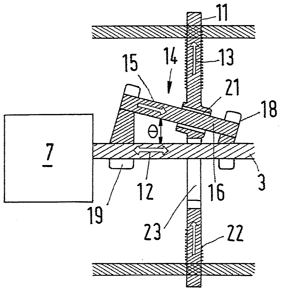
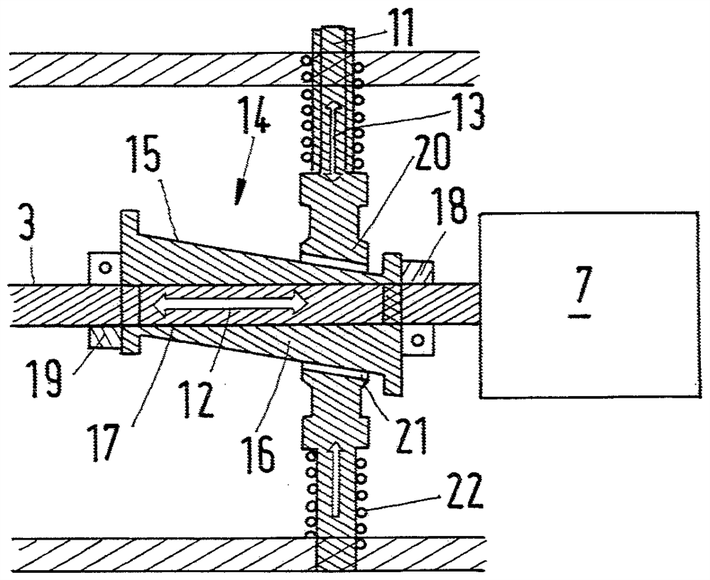
[0029] figure 2 The needle bed 2 with a plurality of drive plungers 3-6 is shown in a somewhat enlarged view. Each drive push rod 3-6 is in connection with a drive motor 7,8. exist figure 1 In the illustration of , the drive motors 7 , 8 are arranged at one end of the warp knitting machine 1 . However, the drive motors 7 , 8 can also be arranged at both ends of the warp knitting machine 1 .
[0030] The drive motors 7, 8 drive the dr...
PUM
 Abstract
Description
Claims
Application Information
 - R&D
- Intellectual Property
- Life Sciences
- Materials
- Tech Scout
- Unparalleled Data Quality
- Higher Quality Content
- 60% Fewer Hallucinations
Browse by: Latest US Patents, China's latest patents, Technical Efficacy Thesaurus, Application Domain, Technology Topic, Popular Technical Reports.
© 2025 PatSnap. All rights reserved.Legal|Privacy policy|Modern Slavery Act Transparency Statement|Sitemap|About US| Contact US: help@patsnap.com


