Supercharge Your Innovation With Domain-Expert AI Agents!

Drilling equipment for petroleum valve accessories

A technology of drilling equipment and valves, which is applied in the direction of drilling/drilling equipment, boring/drilling, metal processing equipment, etc., which can solve the problems of manpower consumption, falling off, danger, etc., to avoid unstable falling, stable Sliding seat, convenient positioning effect

Inactive Publication Date: 2022-01-18
朱娟
View PDF0 Cites 7 Cited by
  • Summary
  • Abstract
  • Description
  • Claims
  • Application Information

AI Technical Summary

Problems solved by technology

[0003] Petroleum valves are composed of multiple accessories, some of which need to be drilled on four sides before they can be used normally. The existing drilling technology for oil valve accessories is generally that the user holds the accessories and uses a high-speed rotating drill to drill holes for them. After drilling on one side, manually push the accessories to rotate 90 degrees to complete the drilling on the four sides of the accessories. However, manually pressing down the drill bit to drill holes for the accessories is not only dangerous but also very labor-intensive. At the same time, manually pushing the accessories to rotate makes the drilling efficiency low. , when the accessories are drilled, the accessories cannot be fixed well, and the inaccurate position of the accessories will also affect the precise drilling of the accessories. When using equipment to drill holes for accessories, some parts may not be stable enough and fall off

Method used


Image

  • Drilling equipment for petroleum valve accessories
  • Drilling equipment for petroleum valve accessories
  • Drilling equipment for petroleum valve accessories

Examples


Embodiment 1

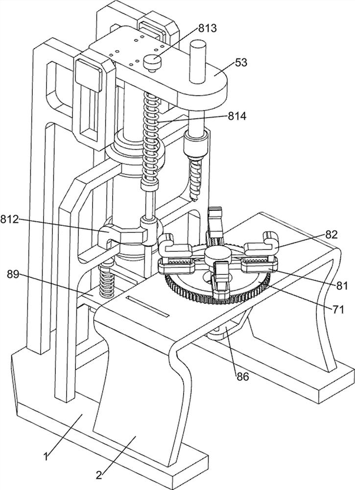
[0027] Such as figure 1 and figure 2 As shown, this embodiment discloses a drilling equipment for petroleum valve accessories, including a base 1, a workbench 2, an installation shaft 3, a drill bit 4, a lifting mechanism 5 and a driving mechanism 6, and the upper front side of the base 1 is connected to a workbench 2. A lifting mechanism 5 is provided on the upper rear side of the base 1, and a mounting shaft 3 is rotatably arranged on the lifting mechanism 5, and a drill bit 4 is connected to the lower side of the mounting shaft 3, and a driving mechanism 6 is provided on the lifting mechanism 5.

[0028] Lifting mechanism 5 comprises support 51, guide rail 52, sliding seat 53, support frame 54 and electric push rod 55, base 1 top rear side is connected with support 51 symmetrically left and right, support 51 top front side is all connected with guide rail 52, between guide rail 52 The sliding seat 53 is slidably connected between them, the sliding seat 53 is connected wit...

Embodiment 2

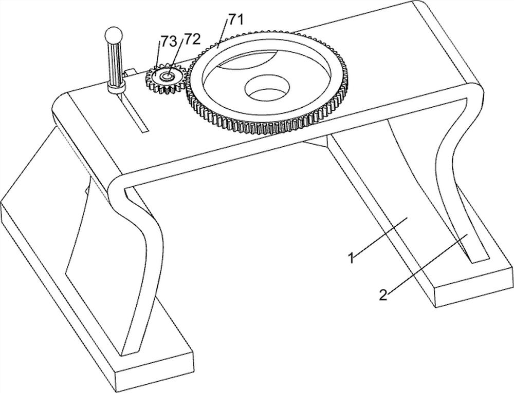
[0032] Such as figure 1 , Figure 3 ~ Figure 8As shown, in some embodiments, a rotating assembly 7 is also included, and the rotating assembly 7 includes a gear ring 71, a rotating shaft 72, a first gear 73, a one-way gear 74, a guide rod 75, a rack 76, a compression spring 77 and The handle 78 is connected to the gear ring 71 in the middle of the top of the workbench 2, and the left rear side of the top of the workbench 2 is connected to the rotating shaft 72. The upper side of the rotating shaft 72 is connected to the first gear 73, and the first gear 73 and the gear ring 71 are mutually connected. meshing, the lower side of the rotating shaft 72 is connected with a one-way gear 74, the upper left side of the workbench 2 is connected with a guide rod 75, and the guide rod 75 is slidably connected with a rack 76, and the rack 76 cooperates with the one-way gear 74, and the rack A compression spring 77 is connected between 76 and the workbench 2, and the compression spring 77...


PUM


Abstract

The invention discloses drilling equipment for petroleum valve accessories. The drilling equipment comprises a base, a lifting mechanism, a mounting shaft, a drill bit and a driving mechanism, wherein a workbench is connected to one side of the upper portion of the base; the lifting mechanism is arranged at one side of the upper portion of the base; the mounting shaft is rotationally arranged on the lifting mechanism; the drill bit is connected to the lower side of the mounting shaft; and the driving mechanism is arranged on the lifting mechanism. The drilling equipment for the petroleum valve accessories has the advantages that the accessories are automatically clamped and fixed, the accessories are easily driven to rotate, the accessories are conveniently positioned, the sliding seat is easily and conveniently operated and stabilized, and equipment parts are prevented from falling off due to instability.

Description

technical field [0001] The invention relates to a drilling device, in particular to a drilling device for petroleum valve fittings. Background technique [0002] Valves refer to the control components in the fluid delivery system, which have the functions of cut-off, regulation, diversion, prevention of reverse flow, pressure stabilization, diversion or overflow pressure relief, etc., while oil valves obviously refer to important components used to control oil delivery . [0003] Petroleum valves are composed of multiple accessories, some of which need to be drilled on four sides before they can be used normally. The existing drilling technology for oil valve accessories is generally that the user holds the accessories and uses a high-speed rotating drill to drill holes for them. After drilling on one side, manually push the accessories to rotate 90 degrees to complete the drilling on the four sides of the accessories. However, manually pressing down the drill bit to drill ...

Claims


Application Information

Patent Timeline
IPC IPC(8): B23B41/00B23Q3/06B23Q7/00B23Q3/18
CPCB23B41/00B23Q3/062B23Q7/00B23Q3/18
Inventor 朱娟
Owner 朱娟
Features
  • R&D
  • Intellectual Property
  • Life Sciences
  • Materials
  • Tech Scout
  • Unparalleled Data Quality
  • Higher Quality Content
  • 60% Fewer Hallucinations
Learn More