Optical lens, camera module and electronic equipment

An optical lens and lens technology, applied in optics, optical components, instruments, etc., can solve the problems of difficult to meet the high-definition imaging requirements of optical lenses, improve the difficulty of lens processing and assembly, and the imaging quality of optical lenses is not clear enough. The effect of forming yield and assembly yield, improving resolution and imaging clarity, and miniaturizing imaging quality

Active Publication Date: 2022-05-17
JIANGXI JINGCHAO OPTICAL CO LTD
View PDF5 Cites 0 Cited by
  • Summary
  • Abstract
  • Description
  • Claims
  • Application Information

AI Technical Summary

Problems solved by technology

However, the increase in the number of lenses increases the difficulty of processing and assembling the lenses, and increases the volume of the optical lens.
Therefore, in the related art, under the design trend of thin, light and miniaturized optical lenses, the image quality of optical lenses is poor, the resolution is low, and the imaging quality of optical lenses is not clear enough, it is difficult to meet people's high-definition requirements of optical lenses. imaging requirements

Method used


Image

  • Optical lens, camera module and electronic equipment
  • Optical lens, camera module and electronic equipment
  • Optical lens, camera module and electronic equipment

Examples


no. 1 example

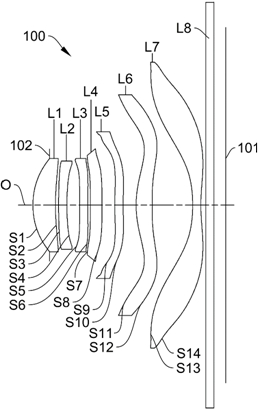
[0064] A schematic structural view of the optical lens 100 disclosed in the first embodiment of the present application, as shown in figure 1 As shown, the optical lens 100 includes a stop 102, a first lens L1, a second lens L2, a third lens L3, a fourth lens L4, a fifth lens L5, a first lens L1, a fourth lens L4, a fifth lens L5, and a first lens L1 arranged sequentially from the object side to the image side along the optical axis O. Six lenses L6, a seventh lens L7 and a filter L8. Among them, the first lens L1 has positive refractive power, the second lens L2 has negative refractive power, the third lens L3 has negative refractive power, the fourth lens L4 has positive refractive power, the fifth lens L5 has negative refractive power, and the sixth lens L6 has positive refractive power, and seventh lens L7 has negative refractive power. Regarding the materials of the first lens L1, the second lens L2, the third lens L3, the fourth lens L4, the fifth lens L5, the sixth len...

no. 2 example

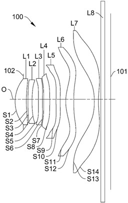
[0078] Please refer to image 3 , image 3 It is a schematic structural diagram of the optical lens 100 according to the second embodiment of the present application. The optical lens 100 includes a stop 102, a first lens L1, a second lens L2, a third lens L3, a fourth lens L4, a fifth lens L5, and a sixth lens L6, which are sequentially arranged from the object side to the image side along the optical axis O , the seventh lens L7 and the filter L8. Among them, the first lens L1 has positive refractive power, the second lens L2 has negative refractive power, the third lens L3 has negative refractive power, the fourth lens L4 has positive refractive power, the fifth lens L5 has negative refractive power, and the sixth lens L6 has positive refractive power, and seventh lens L7 has negative refractive power. Regarding the materials of the first lens L1, the second lens L2, the third lens L3, the fourth lens L4, the fifth lens L5, the sixth lens L6 and the seventh lens L7, plea...

no. 3 example

[0089] Please refer to Figure 5 , Figure 5 A schematic structural diagram of the optical lens 100 according to the third embodiment of the present application is shown. The optical lens 100 includes a diaphragm 102, a first lens L1, a second lens L2, a third lens L3, a fourth lens L4, a fifth lens L5, and a sixth lens L6, which are sequentially arranged from the object side to the image side along the optical axis O , the seventh lens L7 and the filter L8. Among them, the first lens L1 has positive refractive power, the second lens L2 has negative refractive power, the third lens L3 has positive refractive power, the fourth lens L4 has negative refractive power, the fifth lens L5 has positive refractive power, and the sixth lens L6 has positive refractive power, and seventh lens L7 has negative refractive power. Regarding the materials of the first lens L1, the second lens L2, the third lens L3, the fourth lens L4, the fifth lens L5, the sixth lens L6 and the seventh lens...


PUM


Abstract

The optical lens, camera module and electronic equipment disclosed by the present invention, the optical lens includes a first lens, a second lens, a third lens, a fourth lens, a fifth lens, a sixth lens and a seventh lens; the object of the first lens The side and image sides are convex and concave, the object side and image side of the second lens are convex and concave, the image sides of the third lens and the fourth lens are both convex, and the object side and image side of the fifth lens are convex and concave , the object side and image side of the sixth lens are concave and convex, the object side and image side of the seventh lens are both concave, and the optical lens satisfies the following relationship: 6.5mm

Description

technical field [0001] The invention relates to the technical field of optical imaging, in particular to an optical lens, a camera module and electronic equipment. Background technique [0002] At present, with the development of camera technology, people have higher and higher requirements for the imaging quality of optical lenses, which not only requires optical lenses to be thinner, lighter and smaller, but also to achieve higher imaging quality. In order to achieve higher imaging quality, optical lenses need to increase the number of lenses to correct aberrations. However, the increase in the number of lenses increases the difficulty of processing and assembling the lenses, and increases the volume of the optical lens. Therefore, in the related art, under the design trend of thin, light and miniaturized optical lenses, the image quality of optical lenses is poor, the resolution is low, and the imaging quality of optical lenses is not clear enough, it is difficult to mee...

Claims


Application Information

Patent Timeline
Patent Type & Authority Patents(China)
IPC IPC(8): G02B13/00G02B13/06G02B13/18
CPCG02B13/0045G02B13/18G02B13/06
Inventor 李翔宇徐标李明
Owner JIANGXI JINGCHAO OPTICAL CO LTD
Why Eureka
Try Eureka