Power equipment cabinet

A technology for power equipment and cabinets, applied in the field of power distribution equipment, can solve the problems of potential safety hazards and poor dust removal effects in manual dust removal, and achieve the effects of enhancing wind power and enhancing dust removal effects.

Pending Publication Date: 2022-01-18
GUANGDONG POWER GRID CO LTD +1
View PDF0 Cites 0 Cited by
  • Summary
  • Abstract
  • Description
  • Claims
  • Application Information

AI Technical Summary

Problems solved by technology

At present, manual dust removal is often used for power distribution cabinet dust removal.

Method used


Image

  • Power equipment cabinet
  • Power equipment cabinet
  • Power equipment cabinet

Examples


Embodiment 1

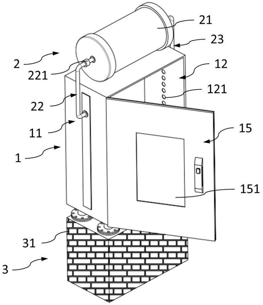
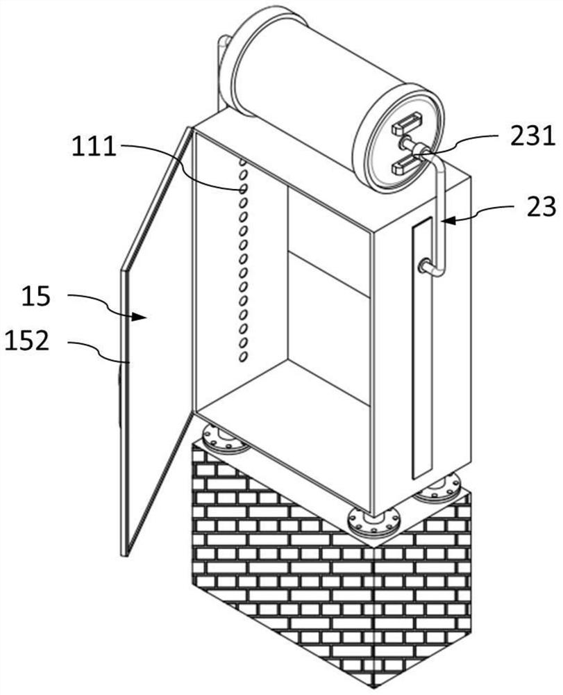
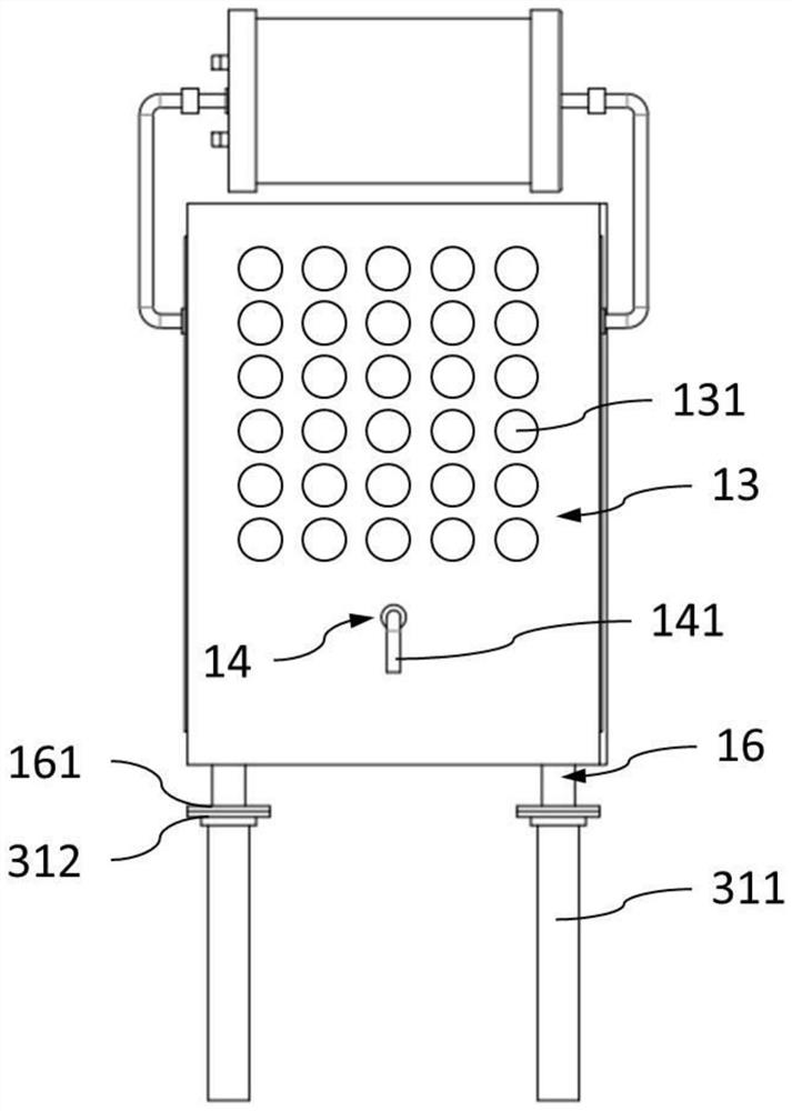
[0030] figure 1 It is the first axonometric view of the power equipment cabinet provided by Embodiment 1 of the present invention, figure 2 It is the second isometric view of the power equipment cabinet provided by Embodiment 1 of the present invention, as shown in Figure 1-2 As shown, this embodiment provides a power equipment cabinet, which includes: a cabinet body 1 and a dust removal mechanism 2 . The dust removal mechanism 2 can quickly and efficiently remove dust from the cabinet body 1 . Specifically, the overall structural outline of the cabinet body 1 is a cuboid or similar cuboid, including a top board, a bottom board, a front board, a rear board, a left board and a right board. In this embodiment, the cabinet body 1 includes a first air blast side plate 11 , a second air blast side plate 12 and an exhaust back plate 13 , and the first air blast side plate 11 and the second air blast side plate 12 are arranged opposite to each other. Preferably, the first air bl...


PUM


Abstract

The invention relates to the technical field of power distribution equipment, and discloses a power equipment cabinet. The power equipment cabinet comprises a cabinet body and a dust removal mechanism, the cabinet body comprises a first air blowing side plate, a second air blowing side plate and an air exhaust back plate, the first air blowing side plate and the second air blowing side plate are oppositely arranged, the first air blowing side plate is provided with a first air inlet hole, and dust accumulation on the leeward side of the circuit element caused by single wind direction is prevented. The bottom end of the air exhaust back plate is provided with the dust exhaust port, so that the dust can be intensively discharged from the dust exhaust port after being blown down. The dust removal mechanism comprises an air pump, an air inlet pipeline, a first exhaust pipeline and a second exhaust pipeline, the first exhaust pipeline communicates with the first air inlet hole, and the second exhaust pipeline communicates with the second air inlet hole. Air is blown into the cabinet body through the air pump to enhance wind power. In the using process, the cabinet door is opened, the first exhaust pipeline and the second exhaust pipeline blow air into the cabinet body at the same time, hedging airflow is generated in the cabinet body, and the dust removal effect is further enhanced.

Description

technical field [0001] The invention relates to the technical field of power distribution equipment, in particular to a power equipment cabinet. Background technique [0002] The power system is a power production and consumption system composed of power generation, power transmission, power transformation, power distribution and power consumption. It converts the primary energy of nature into electricity through the power generation device, and then supplies the electricity to various users through power transmission, transformation and distribution. It mainly includes power generation equipment and power supply equipment. Power generation equipment is mainly power plant boilers, steam turbines, gas turbines, water turbines, generators, motors, transformers, etc. Power supply equipment is mainly transmission lines of various voltage levels, transformers, contactors Wait. Most power generation equipment and power supply equipment are used outdoors, so it is necessary to se...

Claims


Application Information

Patent Timeline
IPC IPC(8): H02B1/28H02B1/56H02B1/30H02B1/32
CPCH02B1/28H02B1/565H02B1/30H02B1/32
Inventor 罗建文黄鑫王志坚陈卓云魏立武
Owner GUANGDONG POWER GRID CO LTD
Why Eureka
Try Eureka