

Full-automatic high-speed silicon wafer inserting machine
A fully automatic technology for inserting silicon wafers, applied to conveyor objects, cleaning methods using gas flow, electrical components, etc., can solve problems such as dust adsorption, affecting the use of silicon wafers, and dust on silicon wafers, so as to improve wind power , the effect of improving fluency
- Summary
- Abstract
- Description
- Claims
- Application Information
AI Technical Summary
Problems solved by technology
Method used
Image

Examples
Embodiment 1
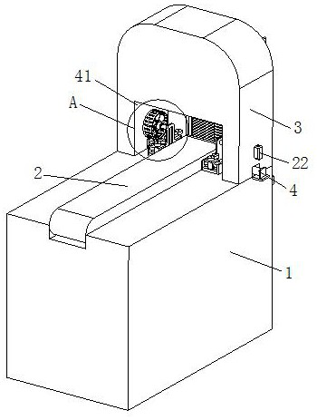
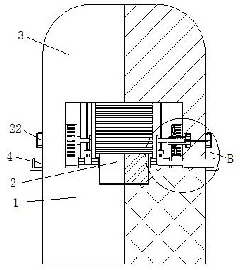
[0034] like Figure 1 to Figure 8 As shown, a fully automatic high-speed silicon chip insertion machine according to the present invention includes a base 1, a conveyor belt 2, a support wall 3, a hydraulic rod 4, a connecting plate 5, a screw rod 6, a screw sleeve 7 and a fan blade 8; The middle part of the top surface of the base 1 is provided with a conveyor belt 2, and the feeding end of the top surface of the base 1 is fixedly connected to the support wall 3, and the bottom end of the support wall 3 is provided with a through groove 41, and both sides of the through groove 41 are provided with Notch, the inside of the notch is fixed to the hydraulic rod 4, the piston rod of the hydraulic rod 4 is fixed to the connecting plate 5, and the top of the connecting plate 5 is connected to the screw rod 6 near the side of the hydraulic rod 4. The middle part of the side wall of the groove 41 is rotated to install the screw sleeve 7, the inner ring of the screw sleeve 7 is threade...
Embodiment 2
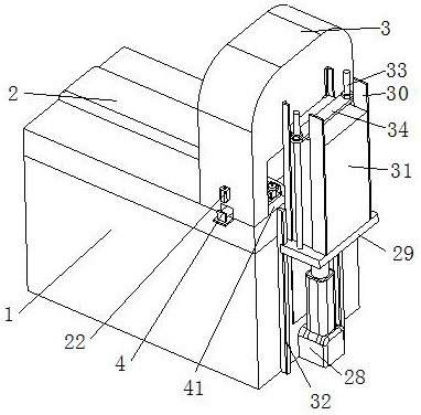
[0043] like Figure 9 to Figure 12 As shown, both sides of the entrance of the storage box 31 are equipped with chute 35, and a baffle plate 36 is slidably installed between the chute 35 on both sides, and a spring 37 is installed at the bottom of the chute 35, and the baffle plate 36 The top is fixedly connected with the movable insert 38, the middle part of the blanking end of the base 1 is fixed with the fixed insert 39, the movable insert 38 is in contact with the fixed insert 39, the top surface of the baffle plate 36 is in contact with the storage box 31. The top of the entrance is inlaid with magnets 40, and the magnets 40 on both sides attract each other; when the storage box 31 is raised, the moving insert 38 is blocked by the fixed insert 39, so that the baffle 36 is blocked, and the spring 37 compresses and accumulates force, and the The storage opening of the storage box 31 is opened, so that the silicon chip that has been cleaned is inserted into the slot. After t...
PUM
 Abstract
Description
Claims
Application Information