

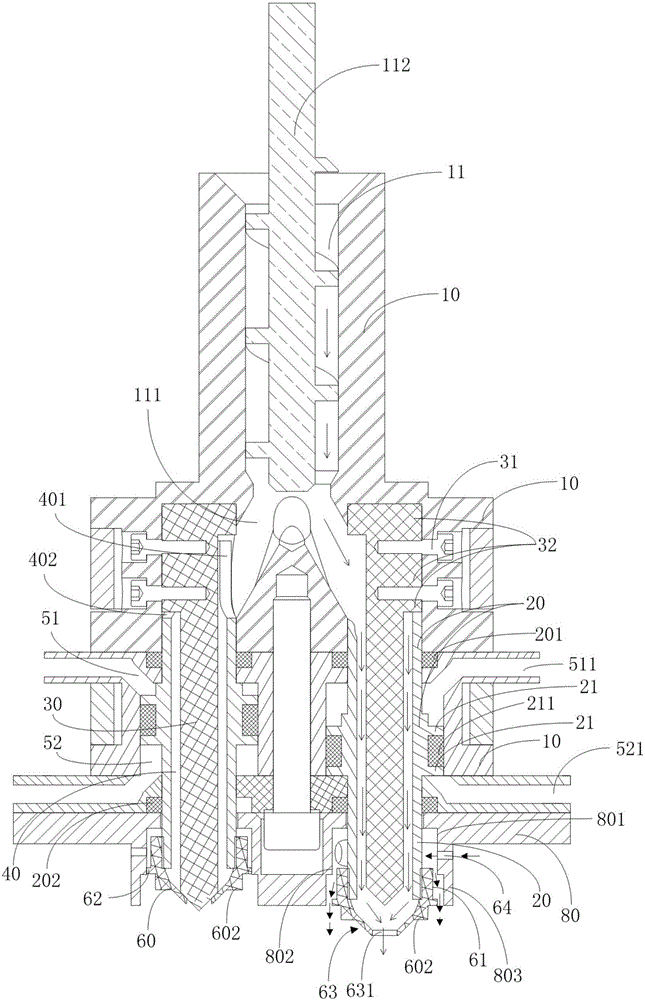
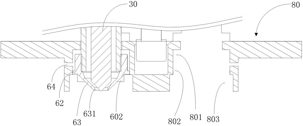
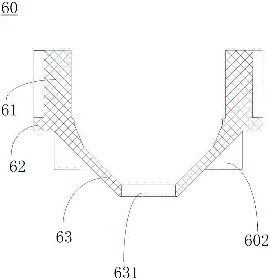
3D printing air nozzle and multi-channel telescopic nozzle valve provided with air nozzle
A 3D printing and air inlet channel technology, applied in the field of 3D printing, can solve the problems of weak cooling effect, excessive wind force, and low accuracy, so as to eliminate the trace influence of excess heat, improve cooling efficiency, and uniform cooling effect Effect
- Summary
- Abstract
- Description
- Claims
- Application Information
AI Technical Summary
Problems solved by technology
Method used
Image

Examples
Embodiment Construction
[0072] Embodiments of the present invention are described in detail below, examples of which are shown in the drawings, wherein the same or similar reference numerals designate the same or similar elements or elements having the same or similar functions throughout. The embodiments described below by referring to the figures are exemplary and are intended to explain the present invention and should not be construed as limiting the present invention.
[0073] In describing the present invention, it should be understood that the terms "center", "longitudinal", "transverse", "length", "width", "thickness", "upper", "lower", "front", " Orientation or position indicated by "back", "left", "right", "vertical", "horizontal", "top", "bottom", "inner", "outer", "clockwise", "counterclockwise", etc. The relationship is based on the orientation or positional relationship shown in the drawings, and is only for the convenience of describing the present invention and simplifying the descrip...
PUM
 Abstract
Description
Claims
Application Information