
Manufacturing process of motor rotor iron core with special-shaped tooth part

A technology of motor rotor and manufacturing process, applied in the direction of motor, manufacturing motor generator, manufacturing stator/rotor body, etc., can solve the problems of non-overlapping of two adjacent iron cores and the inability to manufacture the rotor core of the motor, etc. Reliable and efficient molding

Active Publication Date: 2022-01-18
NINGBO ZHENYU TECH
View PDF6 Cites 0 Cited by
  • Summary
  • Abstract
  • Description
  • Claims
  • Application Information

AI Technical Summary

Problems solved by technology

At present, for the motor rotor core with teeth, each piece needs to be rotated during the forming and stacking process of the iron sheets, so that the two adjacent iron sheets do not overlap. However, the existing technology cannot realize that the two adjacent iron sheets do not overlap. Under the condition of rotation, the motor rotor core cannot be manufactured. Based on the above, the inventor finally has the manufacturing process of the present invention in view of the research and improvement.

Method used


Image

  • Manufacturing process of motor rotor iron core with special-shaped tooth part
  • Manufacturing process of motor rotor iron core with special-shaped tooth part
  • Manufacturing process of motor rotor iron core with special-shaped tooth part

Examples


Embodiment

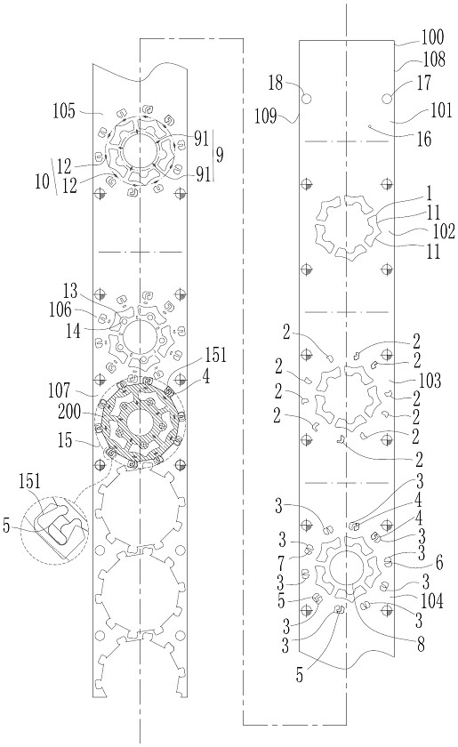
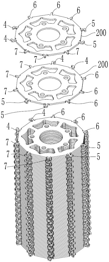
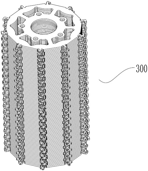
[0023] Such as Figure 1-Figure 3 As shown, the manufacturing process of a motor rotor core with special-shaped teeth described in this embodiment includes the following steps:

[0024] In step S1, the material strip 100 is conveyed in a continuous step-by-step manner between the upper mold and the lower mold of the continuous blanking mold in the direction of blanking, and is punched and formed in the rotor chip forming area of ​​the material strip 100 to form five ring-shaped arrays. The ventilation holes 1, five ventilation holes 1 all include two arc-shaped convex parts 11 located on the outer inner wall; wherein, a continuous step-by-step punching station is formed between the upper die and the lower die of the continuous punching die, and the continuous The step-by-step punching station includes punching guide hole and marking hole station 101, punching ventilation hole station 102, punching first shape hole station 103, punching second Outline hole and shaft hole stati...


PUM


Abstract

The invention discloses a manufacturing process of a motor rotor iron core with a special-shaped tooth part. A material belt sequentially passes through a guide hole and mark hole blanking station, a ventilation hole blanking station, a first appearance hole blanking station, a second appearance hole and shaft hole blanking station, a buckling point blanking station, a small through hole blanking station and a blanking rotating station to continuously form a plurality of iron core pieces, and the iron core pieces do not coincide after being rotated, and are mutually in fixed connection to form a rotor core; the iron core sheets can be rotated under the condition that the two adjacent iron core sheets do not coincide, so that the two adjacent iron core sheets in the iron core obtained through automatic production do not coincide, and automatic production can be effectively carried out to obtain the iron core with the two adjacent iron core sheets not coincide and the special-shaped tooth part; moreover, the forming is reliable, and the efficiency is high.

Description

technical field [0001] The invention relates to the technical field of a motor core manufacturing process for new energy vehicles, in particular to a motor rotor core manufacturing process with special-shaped teeth. Background technique [0002] At present, new energy vehicles are vigorously promoted and further popularized, especially electric vehicles, and the motor core is the heart of the new energy vehicle drive motor, and its manufacture has always attracted people's attention. At present, for the motor rotor core with teeth, each piece needs to be rotated during the forming and stacking process of the iron chips, so that the two adjacent iron chips do not overlap. However, the existing technology cannot realize that the two adjacent iron chips do not overlap. Under normal circumstances, it rotates, so that the motor rotor core cannot be manufactured. Based on the above, the inventor finally has the manufacturing process of the present invention in view of research and...

Claims


Application Information

Patent Timeline
IPC IPC(8): H02K15/02
CPCH02K15/022Y02T10/64
Inventor 邓晓根黄强陈伟力
Owner NINGBO ZHENYU TECH
Features
  • Generate Ideas
  • Intellectual Property
  • Life Sciences
  • Materials
  • Tech Scout
  • Unparalleled Data Quality
  • Higher Quality Content
  • 60% Fewer Hallucinations
Learn More