Flat mop cleaning equipment with transmission mechanism and use method of flat mop cleaning equipment

A technology of cleaning equipment and transmission mechanism, which is applied in cleaning equipment, application, carpet cleaning, etc. It can solve the problems of small hand strength, laborious cleaning of mop buckets, complicated pipeline connection methods, etc., and achieve stable connection and brief pipeline connection methods. Effect

Active Publication Date: 2022-01-21
泉州江豚实业有限公司
View PDF12 Cites 0 Cited by
  • Summary
  • Abstract
  • Description
  • Claims
  • Application Information

AI Technical Summary

Problems solved by technology

[0011] Aiming at the above-mentioned deficiencies in the prior art, the present invention provides a flat mop cleaning device with a transmission mechanism to solve the inability of the prior art to convert the reciprocating motion of the pedal into the power of the flat mop bucket to absorb water; In the prior art, the sewage is transported to the sewage tank, and the clean water is transported to the cleaning tank. The pipeline connection method is complicated, and the function of using the same water transport power to complete the water transport cannot be realized; the mop bucket of the prior art is very laborious to clean, and often The power to move the mop up and down is provided by the hand. The force of the hand is often very small. If you move the mop up and down by hand for a long time to clean the mop, you will often feel very tired.

Method used


Image

  • Flat mop cleaning equipment with transmission mechanism and use method of flat mop cleaning equipment
  • Flat mop cleaning equipment with transmission mechanism and use method of flat mop cleaning equipment
  • Flat mop cleaning equipment with transmission mechanism and use method of flat mop cleaning equipment

Examples


Embodiment 1

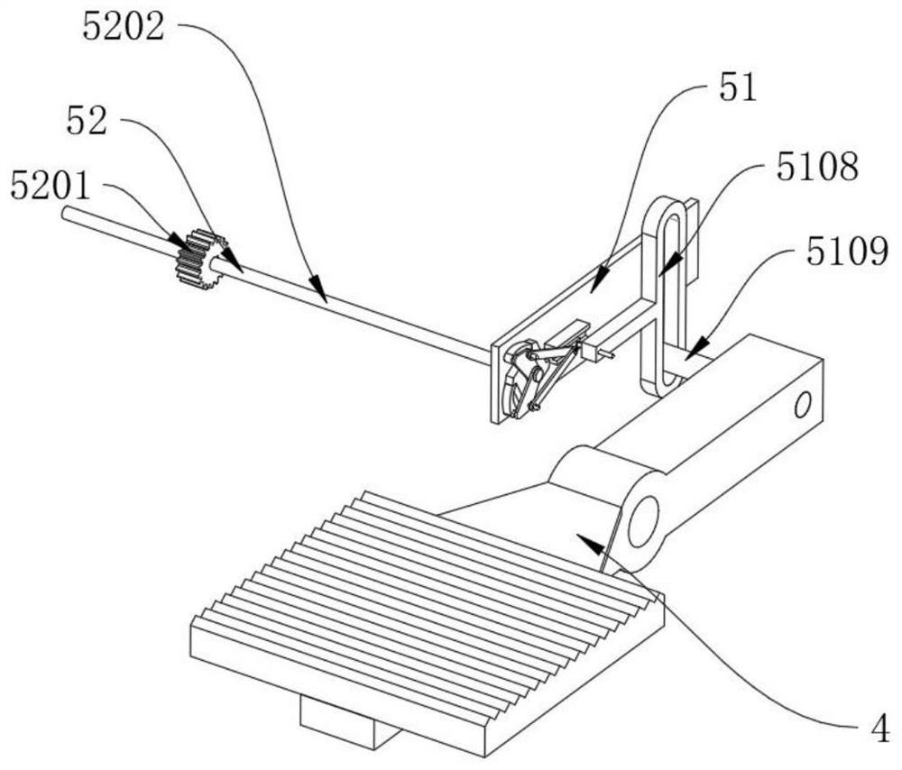
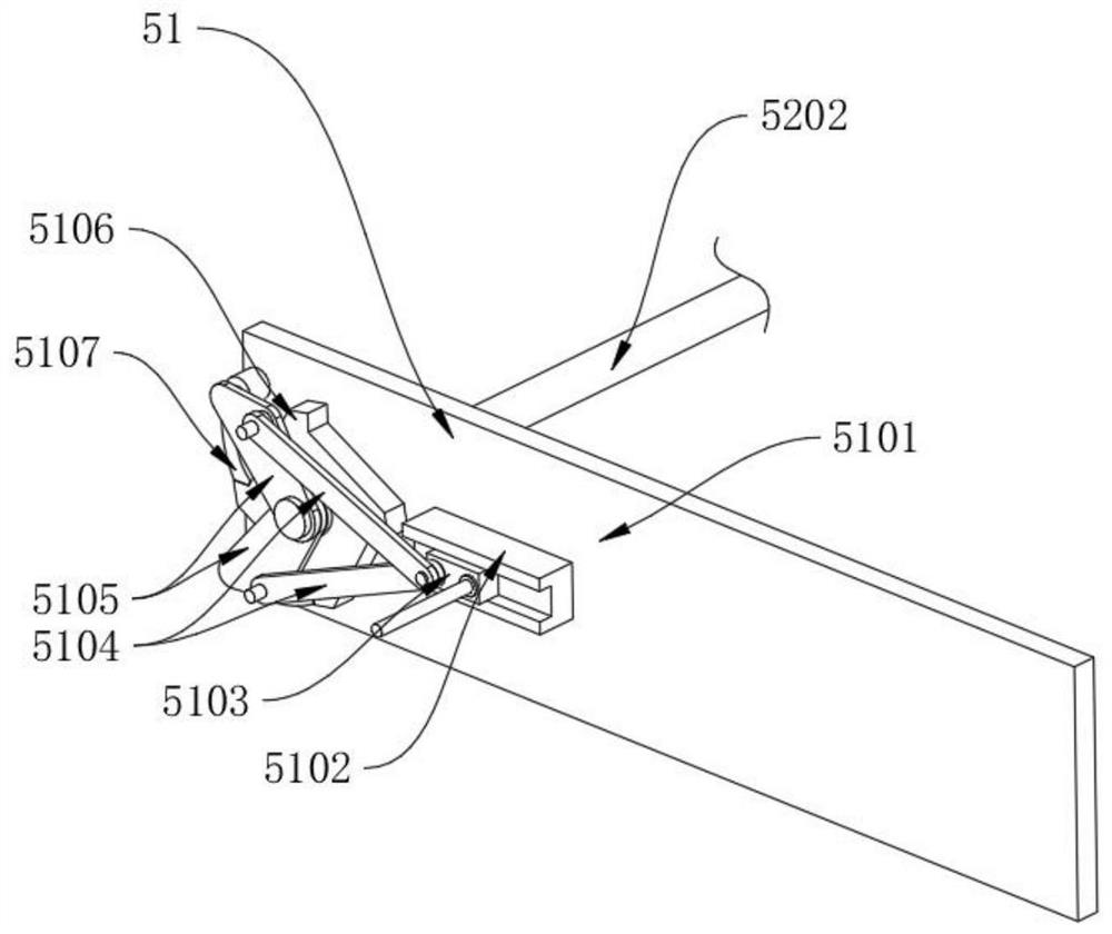
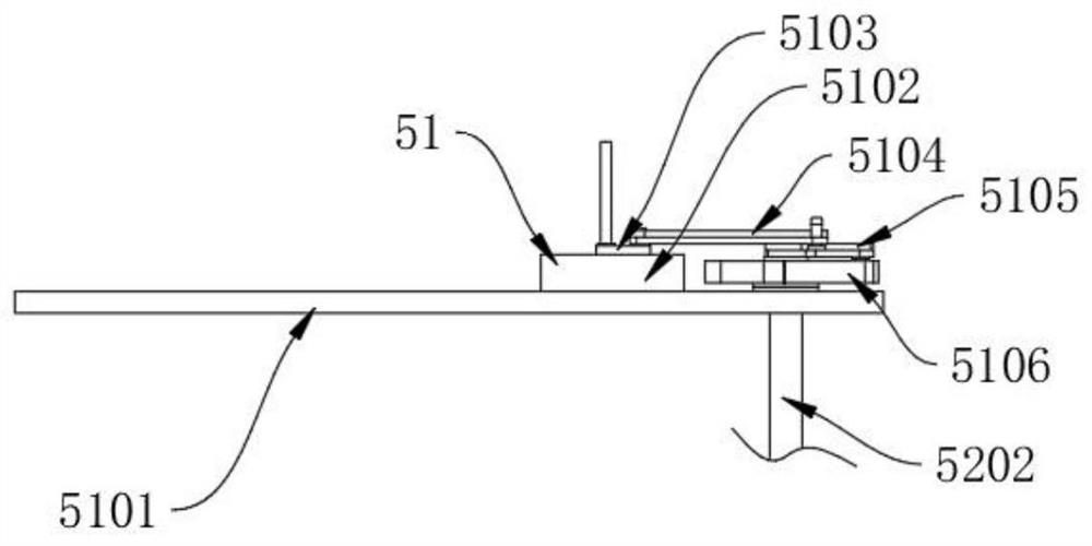
[0044] like Figure 1-7 As shown, a flat mop cleaning device with a transmission mechanism includes an air pressure water injection assembly 5. The air pressure water injection assembly 5 includes a connecting rod ratchet mechanism 51, a transmission gear shaft 52, a clutch 53 and a water pump 54. The connecting rod ratchet mechanism 51 is located on Stepping on the side of the pedal assembly 4, the stepping on the pedal assembly 4 is in transmission connection with the connecting rod ratchet mechanism 51, the transmission gear shaft 52 is arranged on the side of the connecting rod ratchet mechanism 51, the connecting rod ratchet mechanism 51 is in transmission connection with the transmission gear shaft 52, and the clutch 53 is located at transmission gear shaft 52 tops, and transmission gear shaft 52 is transmission-connected with clutch 53, and water pump 54 is located at clutch 53 tops, and clutch 53 is transmission-connected with water pump 54.

[0045] In this embodiment...

Embodiment 2

[0053] This embodiment is a further improvement of the previous embodiment, such as Figure 1-7 As shown, a flat mop cleaning device with a transmission mechanism includes an air pressure water injection assembly 5. The air pressure water injection assembly 5 includes a connecting rod ratchet mechanism 51, a transmission gear shaft 52, a clutch 53 and a water pump 54. The connecting rod ratchet mechanism 51 is located on Stepping on the side of the pedal assembly 4, the stepping on the pedal assembly 4 is in transmission connection with the connecting rod ratchet mechanism 51, the transmission gear shaft 52 is arranged on the side of the connecting rod ratchet mechanism 51, the connecting rod ratchet mechanism 51 is in transmission connection with the transmission gear shaft 52, and the clutch 53 is located at transmission gear shaft 52 tops, and transmission gear shaft 52 is transmission-connected with clutch 53, and water pump 54 is located at clutch 53 tops, and clutch 53 is...


PUM


Abstract

The invention belongs to the technical field of cleaning equipment, and particularly relates to flat mop cleaning equipment with a transmission mechanism, which comprises an air pressure water injection assembly, the air pressure water injection assembly comprises a connecting rod ratchet mechanism, a transmission gear shaft, a clutch and a water pump, the connecting rod ratchet mechanism is arranged on the side part of a treading pedal assembly, the treading pedal assembly is in transmission connection with the connecting rod ratchet mechanism, the transmission gear shaft is arranged on the side portion of the connecting rod ratchet mechanism, the connecting rod ratchet mechanism is in transmission connection with the transmission gear shaft, and the clutch is arranged on the upper portion of the transmission gear shaft. The problems that in the prior art, reciprocating motion of a pedal cannot be converted into power for water absorption of a flat mop bucket; the pipeline connection mode is complex, and all the water conveying functions cannot be achieved through the same water conveying power; the mop is very laborious to clean, and the like are solved. The equipment is easy and convenient to operate, an operator can easily clean a flat mop through the equipment, and sewage and clean water can be easily conveyed.

Description

technical field [0001] The invention belongs to the technical field of cleaning equipment, and in particular relates to a flat mop cleaning equipment with a transmission mechanism and a use method thereof. Background technique [0002] In the prior art, there are three ways to dehydrate the flat mop. The first way is to dehydrate the foot-pressing type, which is provided with a foot-pressing device on the mop bucket. The water squeeze basket, the pedal hinged on the upper part of the mop bucket and opposite to the water squeeze basket, the pedal and the squeeze water basket form a water squeeze space. When dehydrating, the mop on the mop board of the flat mop needs to be removed first, and the mop Place it in the water-squeezing space, and then step on the pedal to shrink the water-squeezing space to squeeze out the water on the mop. This form of dehydration requires the design of a foot-pressing device with a complex structure, which is costly; when squeezing water, the mo...

Claims


Application Information

Patent Timeline
IPC IPC(8): A47L13/58A47L13/59
CPCA47L13/58A47L13/59
Inventor 郭鑫
Owner 泉州江豚实业有限公司
Why Eureka
Try Eureka