Small auxiliary glue injection device for air filter element
A technology of air filter element and glue injection device, which is applied to devices and coatings that apply liquid to the surface, can solve the problems of high energy consumption, laboriousness, danger of pushing and reclaiming materials, etc., so as to speed up the production rate and avoid premature dropout. The effect of reducing and reducing risk
- Summary
- Abstract
- Description
- Claims
- Application Information
AI Technical Summary
Problems solved by technology
Method used
Image
Examples
Embodiment 1
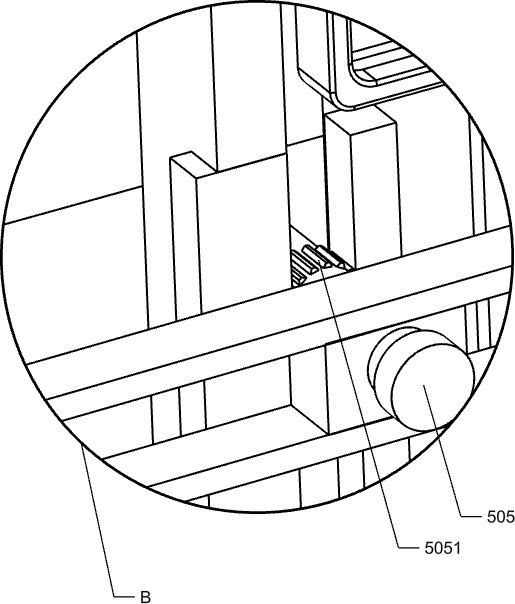
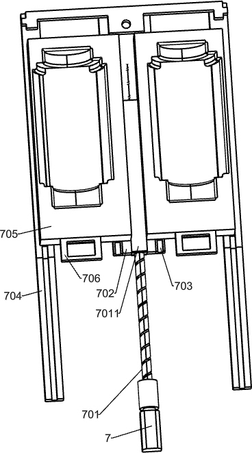
[0033] A small air filter auxiliary injection device, such as Figure 1-4 As shown, it includes a support surface 2, legs 201, a first support column 202, a first support plate 203, a special-shaped support plate 204, a support rod 205, an L-shaped support frame 206, a second support column 207, a fixed frame 211, The third support column 212, the fourth support column 213, the fixed rod 214, the second support plate 215, the cross bar 216, the servo motor 4, the inner slide rail 506, the outer slide rail 507, the reduction motor 7, the second straight slide rail 704 , a material pushing mechanism, a material receiving mechanism and a push-pull mechanism, four legs 201 are installed at the four corners of the lower part of the bracket surface 2, a protruding part is arranged at the front end of the bracket surface 2, and a reduction motor 7 is installed on the protruding part of the front end of the bracket surface 2, The right side of the middle part of the upper surface of t...
Embodiment 2
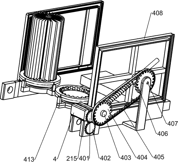
[0036] On the basis of Example 1, such as Figure 6-7 As shown, the pushing mechanism includes a cross bracket 210, a first spur gear 401, a first rotating shaft 403, a first transmission gear 404, a second transmission belt 405, a second transmission gear 406, a fixed shaft 407, and a second rotation shaft 4071, return-shaped track 408, rotating rod 409, first spring 410, slide bar 411, material discharging base 412, the fifth support column 413 and the third spur gear 414, the output shaft of servo motor 4 is connected with the first spur gear 401, the first spur gear 401 meshes with the third spur gear 414, the third spur gear 414 drives the first transmission gear 404 through the first rotating shaft 403, one end of the first rotating shaft 403 is rotationally connected to the fifth support column 413, the The bottom of the five supporting columns 413 is installed on the right rear side of the upper surface of the special-shaped support plate 204, and the first transmissio...
Embodiment 3
[0043] On the basis of Example 2, such as figure 1 with image 3 As shown, it also includes a feeder 3 and a first transmission belt 302, the middle part of the third rotating shaft 415 is connected with the first transmission belt 302, the first transmission belt 302 drives the feeder 3, and the feeder 3 is arranged on the first on the support plate 203.
[0044] After the servo motor 4 starts, the first spur gear 401 rotates with the second spur gear 402, and the second spur gear 402 rotates with the third rotating shaft 415. The middle part of the third rotating shaft 415 is connected with the first transmission belt 302, and the first The transmission belt 302 drives the whole feeder 3 to run, and when the discharge base 412 moves to the right below the feeder 3, it will receive an untreated air filter element to realize the function of automatic feeding.
[0045] Such as Figure 4-5 As shown, it also includes a rotating material blocking plate 301, a torsion spring 301...
PUM
 Abstract
Description
Claims
Application Information
 - R&D
- Intellectual Property
- Life Sciences
- Materials
- Tech Scout
- Unparalleled Data Quality
- Higher Quality Content
- 60% Fewer Hallucinations
Browse by: Latest US Patents, China's latest patents, Technical Efficacy Thesaurus, Application Domain, Technology Topic, Popular Technical Reports.
© 2025 PatSnap. All rights reserved.Legal|Privacy policy|Modern Slavery Act Transparency Statement|Sitemap|About US| Contact US: help@patsnap.com


