Check patentability & draft patents in minutes with Patsnap Eureka AI!

Secondary slide core-pulling mechanism of injection mold

A technology for injection molds and core-pulling mechanisms, which is applied in the field of secondary row-position core-pulling mechanisms, can solve problems such as easy failure, mold core damage, and potential safety hazards, and achieve the effect of small limitations and high practicability

Active Publication Date: 2022-01-21
广东鑫硕精密科技有限公司
View PDF11 Cites 1 Cited by
  • Summary
  • Abstract
  • Description
  • Claims
  • Application Information

AI Technical Summary

Problems solved by technology

However, this method of one-time lateral core-pulling and demoulding is easy to stick to the row position and cause product deformation, while the structure of the row-position secondary core-pulling is generally used to use springs to withstand the inserts to puncture or make two rows. Delay, but the spring of this structure is easily damaged, easy to fail and damage the core of the mold, there is a safety hazard, which is not conducive to the mass production of molds, and this structure is unstable, there is no mechanical fixing method, and there is a risk of synchronous movement of the two rows. Difficult to achieve secondary core pulling

Method used


Image

  • Secondary slide core-pulling mechanism of injection mold
  • Secondary slide core-pulling mechanism of injection mold
  • Secondary slide core-pulling mechanism of injection mold

Examples


Embodiment 1

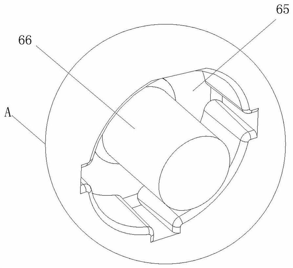
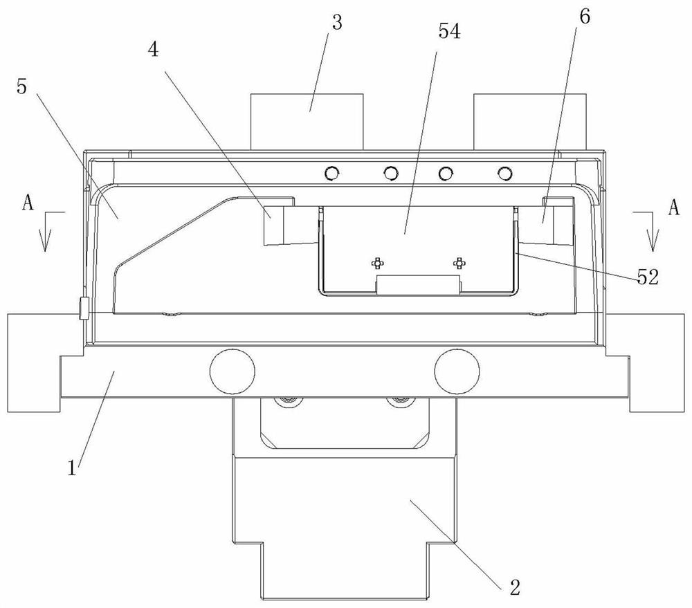
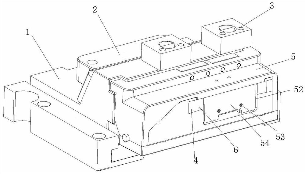
[0032] Embodiment one, such as Figure 1 to Figure 13 As shown, an injection mold for the battery box cover of a car refrigerator includes an injection upper mold 10, an injection lower mold 20, and a secondary row core-pulling mechanism, and the secondary row core-pulling mechanism includes a sliding device arranged under the injection molding The large row slide block 1 on the mold 20 and the delayed large shovel base 2 and two small shovel bases 3 installed on the injection molding upper mold 10, the position of the large row slide block 1 corresponding to the delayed large shovel base 2 is provided with The driven hole 11, the two small shovel bases 3 are provided with a diagonal support pin 31, and the large row slider 1 is provided with two small row sliders 4, two inner inserts 6 and outer inserts. Part 5, the position corresponding to the slanting support pin 31 on the small row position slider 4 is provided with a driven oblique hole 41, the outer insert 5 is arranged...


PUM


Abstract

The invention relates to the technical field of core-pulling mechanisms of injection molds, and discloses a secondary slide core-pulling mechanism of an injection mold. The secondary slide core-pulling mechanism of the injection mold comprises a large slide sliding block arranged on a lower injection mold in a sliding manner, and a delay large shovel base and a small shovel base which are arranged on an upper injection mold, the large slide sliding block is provided with a small slide sliding block, an inner insert and an outer insert, and the small slide sliding block is horizontally arranged in the large slide sliding block in a sliding manner in the sliding direction of the large slide sliding block. When the injection mold is opened, the small shovel base firstly drives the small slide sliding block to retreat, the small slide sliding block and the inner insert are firstly separated from an injection molding part, one-time core pulling is achieved, then the delay large shovel base drives the large slide sliding block to retreat, and the large slide sliding block is driven to drive the outer insert and the inner insert to be separated from the injection molding part as a whole. According to the secondary slide core-pulling mechanism of the injection mold, the secondary core-pulling action is effectively and stably realized, so that the problems that when a plastic product with a through hole, a boss or a groove on the side surface is demolded, slide of the product is stuck, and the product is damaged and broken due to pulling during demolding and core-pulling are solved.

Description

technical field [0001] The invention relates to the technical field of a core-pulling mechanism of an injection mold, in particular to a secondary position core-pulling mechanism of an injection mold. Background technique [0002] Plastic mold is the abbreviation of a combined mold for compression molding, extrusion molding, injection, blow molding and low foam molding. A series of plastic parts of different shapes and sizes can be processed through the coordinated change of the mold convex, concave mold and auxiliary molding system. The positioning mechanism is a structure widely used in plastic molds. It refers to the mechanism that can obtain side core pulling or side parting and reset action to get out of the undercut, depression and other positions of the product. Utilize the forming mold opening action to make the brace pin and the slider produce a relative movement trend, and make the slider move in two forms along the mold opening direction and the horizontal direct...

Claims


Application Information

Patent Timeline
IPC IPC(8): B29C45/33B29C45/44
CPCB29C45/33B29C45/44
Inventor 谢传海王东平谢俊祯戴振朋唐锐
Owner 广东鑫硕精密科技有限公司
Features
  • R&D
  • Intellectual Property
  • Life Sciences
  • Materials
  • Tech Scout
  • Unparalleled Data Quality
  • Higher Quality Content
  • 60% Fewer Hallucinations
Learn More